Page 449 - Marks Calculation for Machine Design
P. 449
P2: Sanjay
        P1: Shibu/Rakesh
                                      15:34
                          January 4, 2005
        Brown.cls
                 Brown˙C10
                              U.S. Customary  MACHINE MOTION      SI/Metric       431
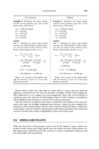
                    Example 4. Determine the output angular  Example 4. Determine the output angular
                    velocity for the planetary gear train as that  velocity for the planetary gear train as that
                    shown in Fig. 10.20, where         shown in Fig. 10.20, where
                      ω B = 1,800 rpm (input)           ω B = 1,800 rpm (input)
                      N A = 64 teeth                    N A = 64 teeth
                      N D = 192 teeth                   N D = 192 teeth
                      N E = 80 teeth                    N E = 80 teeth
                      N F = 48 teeth                     N F = 48 teeth
                    solution                           solution
                    Step 1. Substitute the given input angular  Step 1. Substitute the given input angular
                    velocity (ω B ) and the number of teeth on gears  velocity (ω B ) and the number of teeth on gears
                    (A), (D), (E), and (F) in Eq. (10.49) to calcu-  (A), (D), (E), and (F) in Eq. (10.49) to calcu-
                    late the output angular velocity (ω F ) as  late the output angular velocity (ω F ) as

                          N A + N E  N D                     N A + N E  N D
                     ω F =           − 1 ω B            ω F =           − 1 ω B
                            N F   N A                          N F   N A
                          (64 + 80) teeth     192 teeth      (64 + 80) teeth    192 teeth
                        =                    − 1           =                   − 1
                            48 teeth  64 teeth                 48 teeth  64 teeth
                          ×(1,800 rpm)                       ×(1,800 rpm)
                        = (3)(3 − 1)(1,800 rpm)            = (3)(3 − 1)(1,800 rpm)
                        = (6)(1,800 rpm) = 10,800 rpm      = (6)(1,800 rpm) = 10,800 rpm
                     There is a 6:1 increase in the angular speed,  There is a 6:1 increase in the angular speed,
                    with the direction of gear (F) in the same  with the direction of gear (F) in the same
                    direction as arm (B).              direction as arm (B).


                      Realize that to achieve the same input to output ratio 6:1 using a spur gear train, the
                    input gear would have to be six times the diameter, or number of teeth, as the output gear.
                    This would not be a very compact gear train arrangement. Again, this is the advantage of
                    a planetary gear train; however, its disadvantage is that it is more complex to manufacture
                    and maintain the close tolerances necessary for its efficient operation.
                      One last comment on planetary gear trains. To distribute the loading on the ring gear,
                    many times there are multiple compound gears driving a single sun gear, resulting in a
                    rotating arm with multiple spokes. However, this would not change the input to output ratio
                    of the angular velocities; therefore, the principles and formulas presented in this section are
                    valid for even the most complex configuration of gears and rotating arms.


                   10.4  WHEELS AND PULLEYS


                    While the discussion in the previous section involved the motion of gears, which were
                    treated as both rotating and rolling wheels, here the motion of wheels rolling freely on a
                    flat rough surface will be discussed. The velocity at a variety of important locations around
                    the rolling wheel will be presented.

