
Page 448 - Marks Calculation for Machine Design
P. 448
P2: Sanjay
P1: Shibu/Rakesh
January 4, 2005
Brown.cls
Brown˙C10
430
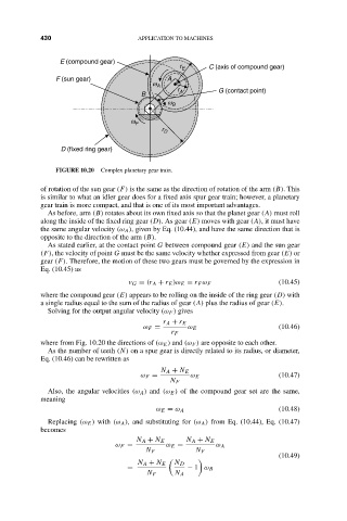
E (compound gear) 15:34 APPLICATION TO MACHINES
r E C (axis of compound gear)
F (sun gear) A
w A
r G (contact point)
B A
w B
w F
r D
D (fixed ring gear)
FIGURE 10.20 Complex planetary gear train.
of rotation of the sun gear (F) is the same as the direction of rotation of the arm (B). This
is similar to what an idler gear does for a fixed axis spur gear train; however, a planetary
gear train is more compact, and that is one of its most important advantages.
As before, arm (B) rotates about its own fixed axis so that the planet gear (A) must roll
along the inside of the fixed ring gear (D). As gear (E) moves with gear (A), it must have
the same angular velocity (ω A ), given by Eq. (10.44), and have the same direction that is
opposite to the direction of the arm (B).
As stated earlier, at the contact point G between compound gear (E) and the sun gear
(F), the velocity of point G must be the same velocity whether expressed from gear (E) or
gear (F). Therefore, the motion of these two gears must be governed by the expression in
Eq. (10.45) as
v G = (r A + r E )ω E = r F ω F (10.45)
where the compound gear (E) appears to be rolling on the inside of the ring gear (D) with
a single radius equal to the sum of the radius of gear (A) plus the radius of gear (E).
Solving for the output angular velocity (ω F ) gives
r A + r E
ω F = ω E (10.46)
r F
where from Fig. 10.20 the directions of (ω E ) and (ω F ) are opposite to each other.
As the number of teeth (N) on a spur gear is directly related to its radius, or diameter,
Eq. (10.46) can be rewritten as
N A + N E
ω F = ω E (10.47)
N F
Also, the angular velocities (ω A ) and (ω E ) of the compound gear set are the same,
meaning
ω E = ω A (10.48)
Replacing (ω E ) with (ω A ), and substituting for (ω A ) from Eq. (10.44), Eq. (10.47)
becomes
N A + N E N A + N E
ω F = ω E = ω A
N F N F
(10.49)
N A + N E N D
= − 1 ω B
N F N A