
Page 453 - Marks Calculation for Machine Design
P. 453
P2: Sanjay
P1: Shibu/Rakesh
January 4, 2005
15:34
Brown.cls
Brown˙C10
U.S. Customary MACHINE MOTION SI/Metric 435
Step2. Substitutethegivenvelocity(v A )ofthe Step2. Substitutethegivenvelocity(v A )ofthe
center of the wheel in Eq. (10.56) to determine center of the wheel in Eq. (10.56) to determine
the angle (θ) as the angle (θ) as
rω sin 45 ◦ rω sin 45 ◦
tan θ = tan θ =
v A − rω cos 45 ◦ v A − rω cos 45 ◦
v A sin 45 ◦ v A sin 45 ◦
= =
v A − v A cos 45 ◦ v A − v A cos 45 ◦
sin 45 ◦ sin 45 ◦
= = 2.414 = = 2.414
1 − cos 45 ◦ 1 − cos 45 ◦
θ = 67.5 ◦ θ = 67.5 ◦
The velocity (v H ) is to the right at the mag- The velocity (v H ) is to the right at the mag-
nitude calculated in step 1 at the angle (θ) nitude calculated in step 1 at the angle (θ)
calculated in step 2 above the horizontal. calculated in step 2 above the horizontal.
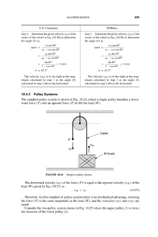
10.4.2 Pulley Systems
The simplest pulley system is shown in Fig. 10.24, where a single pulley transfers a down-
ward force (P) into an upward force (P) to lift the load (W).
Cable
P
v W
v P
W (load)
FIGURE 10.24 Simplest pulley system.
The downward velocity (v P ) of the force (P) is equal to the upward velocity (v W ) of the
load (W) given by Eq. (10.57) as
v W = v P (10.57)
Therefore, for this simplest of pulley systems there is no mechanical advantage, meaning
the force (P) is the same magnitude as the load (W), and the velocities (v P ) and (v W ) are
equal.
Consider the two pulley system shown in Fig. 10.25 where the upper pulley (1) is twice
the diameter of the lower pulley (2).