
Page 444 - Marks Calculation for Machine Design
P. 444
P2: Sanjay
P1: Shibu/Rakesh
January 4, 2005
Brown˙C10
Brown.cls
426
U.S. Customary 15:34 APPLICATION TO MACHINES SI/Metric
Example 1. Determine the output angular Example 1. Determine the output angular
velocity for a basic spur gear train as that shown velocity for a basic spur gear train as that shown
in Fig. 10.17, where in Fig. 10.17, where
ω A = 600 rpm (input) ω A = 600 rpm (input)
N A = 15 teeth N A = 15 teeth
N B = 45 teeth N B = 45 teeth
solution solution
Step 1. Substitute the given input angular Step 1. Substitute the given input angular
velocity (ω A ) and the number of teeth on each velocity (ω A ) and the number of teeth on each
gear in Eq. (10.35) to determine the output gear in Eq. (10.35) to determine the output
angular velocity (ω B ) as angular velocity (ω B ) as
N A (15 teeth) N A (15 teeth)
ω B = ω A = (600 rpm) ω B = ω A = (600 rpm)
N B (45 teeth) N B (45 teeth)
1 1
= (600 rpm) = 200 rpm = (600 rpm) = 200 rpm
3 3
Remember, the direction of gear (B) will be Remember, the direction of gear (B) will be
opposite to the direction of gear (A). opposite to the direction of gear (A).
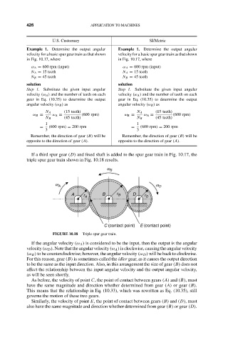
If a third spur gear (D) and fixed shaft is added to the spur gear train in Fig. 10.17, the
triple spur gear train shown in Fig. 10.18 results.
w B
w A w D
A r A B r B D r D
C (contact point) E (contact point)
FIGURE 10.18 Triple spur gear train.
If the angular velocity (ω A ) is considered to be the input, then the output is the angular
velocity (ω D ). Note that the angular velocity (ω A ) is clockwise, causing the angular velocity
(ω B ) to be counterclockwise; however, the angular velocity (ω D ) will be back to clockwise.
For this reason, gear (B) is sometimes called the idler gear, as it causes the output direction
to be the same as the input direction. Also, in this arrangement the size of gear (B) does not
affect the relationship between the input angular velocity and the output angular velocity,
as will be seen shortly.
As before, the velocity of point C, the point of contact between gears (A) and (B), must
have the same magnitude and direction whether determined from gear (A) or gear (B).
This means that the relationship in Eq. (10.33), which was rewritten as Eq. (10.35), still
governs the motion of these two gears.
Similarly, the velocity of point E, the point of contact between gears (B) and (D), must
also have the same magnitude and direction whether determined from gear (B) or gear (D).