
Page 439 - Marks Calculation for Machine Design
P. 439
P2: Sanjay
P1: Shibu/Rakesh
15:34
January 4, 2005
Brown.cls
Brown˙C10
U.S. Customary MACHINE MOTION SI/Metric 421
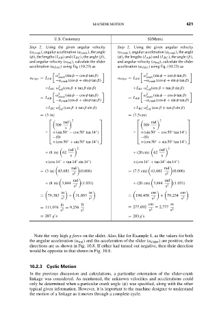
Step 2. Using the given angular velocity Step 2. Using the given angular velocity
(ω crank ), angular acceleration (α crank ), the angle (ω crank ), angular acceleration (α crank ), the angle
(φ), the lengths (L AB ) and (L BC ), the angle (β), (φ), the lengths (L AB ) and (L BC ), the angle (β),
and angular velocity (ω rod ), calculate the slider and angular velocity (ω rod ), calculate the slider
acceleration (a slider ) using Eq. (10.23) as acceleration (a slider ) using Eq. (10.23) as
2 2
ω (sin φ − cos φ tan β) ω (sin φ − cos φ tan β)
a slider = L AB crank a slider = L AB crank
−α crank (cos φ + sin φ tan β) −α crank (cos φ + sin φ tan β)
+L BC ω 2 rod (cos β + tan β sin β) +L BC ω 2 rod (cos β + tan β sin β)
2 2
ω (sin φ − cos φ tan β) ω (sin φ − cos φ tan β)
= L AB crank = L AB crank
−α crank (cos φ + sin φ tan β) −α crank (cos φ + sin φ tan β)
+L BC ω 2 rod (cos β + tan β sin β) +L BC ω 2 rod (cos β + tan β sin β)
= (3in) = (7.5cm)
2 2
rad rad
209 209
s s
◦ ◦ ◦ ◦
× ◦ × ◦
×(sin 50 − cos 50 tan 14 ) ×(sin 50 − cos 50 tan 14 )
−(0) −(0)
◦
◦
◦
◦
◦
◦
×(cos 50 + sin 50 tan 14 ) ×(cos 50 + sin 50 tan 14 )
2 2
rad rad
+ (8in) 62 + (20 cm) 62
s s
◦
◦
◦
◦
◦
×(cos 14 + tan 14 sin 14 ) ×(cos 14 + tan 14 sin 14 )
◦
rad rad
= (3in) 43,681 (0.606) = (7.5cm) 43,681 (0.606)
s 2 s 2
rad rad
+ (8in) 3,844 (1.031) + (20 cm) 3,844 (1.031)
s 2 s 2
in in cm cm
= 79,383 + 31,693 = 198,458 + 79,234
s 2 s 2 s 2 s 2
in ft cm m
= 111,076 = 9,256 = 277,692 = 2,777
s 2 s 2 s 2 s 2
= 287 g s = 283 g s
Note the very high g force on the slider. Also, like for Example 1, as the values for both
the angular acceleration (α rod ) and the acceleration of the slider (a slider ) are positive, their
directions are as shown in Fig. 10.8. If either had turned out negative, then their direction
would be opposite to that shown in Fig. 10.8.
10.2.3 Cyclic Motion
In the previous discussion and calculations, a particular orientation of the slider-crank
linkage was considered. As mentioned, the unknown velocities and accelerations could
only be determined when a particular crank angle (φ) was specified, along with the other
typical given information. However, it is important to the machine designer to understand
the motion of a linkage as it moves through a complete cycle.