
Page 442 - Marks Calculation for Machine Design
P. 442
P2: Sanjay
P1: Shibu/Rakesh
15:34
January 4, 2005
Brown˙C10
Brown.cls
APPLICATION TO MACHINES
424
f = 180°
C
A
b
90°
L AB
L BC
B
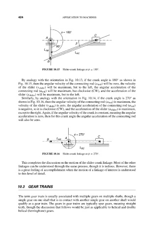
FIGURE 10.15 Slider-crank linkage at φ = 180 . ◦
◦
By analogy with the orientation in Fig. 10.13, if the crank angle is 180 as shown in
Fig. 10.15, then the angular velocity of the connecting rod (ω rod ) will be zero, the velocity
of the slider (v slider ) will be maximum, but to the left, the angular acceleration of the
connecting rod (α rod ) will be maximum, but clockwise (CW), and the acceleration of the
slider (a slider ) will be maximum, but to the left.
Similarly, by analogy with the orientation in Fig. 10.14, if the crank angle is 270 as
◦
shown in Fig. 10.16, then the angular velocity of the connecting rod (ω rod ) is maximum, the
velocity of the slider (v slider ) is zero, the angular acceleration of the connecting rod (α rod )
is negative, so it is clockwise (CW), and the acceleration of the slider (a slider ) is maximum,
excepttotheright.Again,iftheangularvelocityofthecrankisconstant,meaningtheangular
acceleration is zero, then for this crank angle the angular acceleration of the connecting rod
will also be zero.
f = 270°
L A C
B AB
L BC
FIGURE 10.16 Slider-crank linkage at φ = 270 . ◦
This completes the discussion on the motion of the slider-crank linkage. Most of the other
linkages can be understood through the same process, though it is tedious. However, there
is a great feeling of accomplishment when the motion of a linkage of interest is understood
to this level of detail.
10.3 GEAR TRAINS
The term gear train is usually associated with multiple gears on multiple shafts, though a
single gear on one shaft that is in contact with another single gear on another shaft would
qualify as a gear train. The gears in gear trains are typically spur gears, meaning straight
teeth, though the discussion that follows would be just as applicable to helical and double
helical (herringbone) gears.