
Page 440 - Marks Calculation for Machine Design
P. 440
P2: Sanjay
P1: Shibu/Rakesh
Brown.cls
15:34
January 4, 2005
Brown˙C10
422
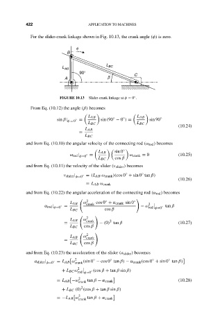
For the slider-crank linkage shown in Fig. 10.13, the crank angle (φ) is zero.
f APPLICATION TO MACHINES
B
L
L AB BC
90°
A b C
◦
FIGURE 10.13 Slider-crank linkage at φ = 0 .
From Eq. (10.12) the angle (β) becomes
L AB L AB
◦
◦
sin β| φ = 0 ◦ = sin(90 − 0 ) = sin 90 ◦
L BC L BC
(10.24)
L AB
=
L BC
and from Eq. (10.10) the angular velocity of the connecting rod (ω rod ) becomes
◦
L AB sin 0
ω rod | φ=0 ◦ = ω crank = 0 (10.25)
L BC cos β
and from Eq. (10.11) the velocity of the slider (v slider ) becomes
◦
◦
v slider | φ=0 ◦ = (L AB ω crank )(cos 0 + sin 0 tan β)
(10.26)
= L AB ω crank
and from Eq. (10.22) the angular acceleration of the connecting rod (α rod ) becomes
2
◦
L AB ω crank cos 0 + α crank sin 0 ◦
α rod | φ=0 ◦ = − ω 2 ◦ tan β
rod φ=0
L BC cos β
2
L AB ω crank 2
= − (0) tan β (10.27)
L BC cos β
2
L AB ω crank
=
L BC cos β
and from Eq. (10.23) the acceleration of the slider (a slider ) becomes
2 ◦ ◦ ◦ ◦
a slider | φ=0 ◦ = L AB ω crank (sin 0 − cos 0 tan β) − α crank (cos 0 + sin 0 tan β)
+ L BC ω 2 ◦ (cos β + tan β sin β)
rod φ=0
2
= L AB −ω (10.28)
crank tan β − α crank
2
+ L BC (0) (cos β + tan β sin β)
2
=−L AB ω
crank tan β + α crank