
Page 446 - Marks Calculation for Machine Design
P. 446
P2: Sanjay
P1: Shibu/Rakesh
January 4, 2005
15:34
Brown.cls
Brown˙C10
428
APPLICATION TO MACHINES
Any number of spur-type gears on any number of fixed parallel shafts can be approached
using this fundamental principle that the velocity of the contact points between any two
gears must be the same from each gear’s perspective.
10.3.2 Planetary Gears
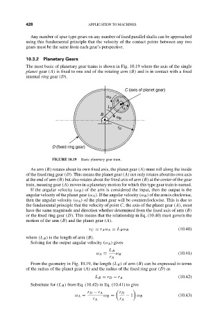
The most basic of planetary gear trains is shown in Fig. 10.19 where the axis of the single
planet gear (A) is fixed to one end of the rotating arm (B) and is in contact with a fixed
internal ring gear (D).
C (axis of planet gear)
w A
A
L B r A
B
w B
r D
D (fixed ring gear)
FIGURE 10.19 Basic planetary gear train.
As arm (B) rotates about its own fixed axis, the planet gear (A) must roll along the inside
of the fixed ring gear (D). This means the planet gear (A) not only rotates about its own axis
at the end of arm (B) but also rotates about the fixed axis of arm (B) at the center of the gear
train, meaning gear (A) moves in a planetary motion for which this type gear train is named.
If the angular velocity (ω B ) of the arm is considered the input, then the output is the
angular velocity of the planet gear (ω A ). If the angular velocity (ω B ) of the arm is clockwise,
then the angular velocity (ω A ) of the planet gear will be counterclockwise. This is due to
the fundamental principle that the velocity of point C, the axis of the planet gear (A), must
have the same magnitude and direction whether determined from the fixed axis of arm (B)
or the fixed ring gear (D). This means that the relationship in Eq. (10.40) must govern the
motion of the arm (B) and the planet gear (A).
v C = r A ω A = L B ω B (10.40)
where (L B ) is the length of arm (B).
Solving for the output angular velocity (ω A ) gives
L B
ω A = ω B (10.41)
r A
From the geometry in Fig. 10.19, the length (L B ) of arm (B) can be expressed in terms
of the radius of the planet gear (A) and the radius of the fixed ring gear (D) as
L B = r D − r A (10.42)
Substitute for (L B ) from Eq. (10.42) in Eq. (10.41) to give
r D − r A r D
ω A = ω B = − 1 ω B (10.43)
r A r A