
Page 434 - Marks Calculation for Machine Design
P. 434
P2: Sanjay
P1: Shibu/Rakesh
January 4, 2005
Brown.cls
Brown˙C10
416
U.S. Customary 15:34 APPLICATION TO MACHINES SI/Metric
Step 3. Using the angular velocity (ω crank ) Step 3. Using the angular velocity (ω crank )
foundinstep1,theangle(β)foundinstep2,and foundinstep1,theangle(β)foundinstep2,and
the given lengths (L AB ) and (L BC ), calculate the given lengths (L AB ) and (L BC ), calculate
the angular velocity (ω rod ) using Eq. (10.10) as the angular velocity (ω rod ) using Eq. (10.10) as
sin φ sin φ
L AB L AB
ω rod = ω crank ω rod = ω crank
L BC cos β L BC cos β
◦ ◦
3in sin 50 rad 7.5cm sin 50 rad
= 209 = 209
8in cos 14 ◦ s 20 cm cos 14 ◦ s
rad rad
= (0.375)(0.7895) 209 = (0.375)(0.7895) 209
s s
rad 1rev 60 s rad 1rev 60 s
= 62 × × = 62 × ×
s 2π rad 1 min s 2π rad 1 min
= 592 rpm = 592 rpm
Step 4. Using the angular velocity (ω crank ) Step 4. Using the angular velocity (ω crank )
found in step 1, the angle (β) found in step 2, found in step 1, the angle (β) found in step 2,
and the given length (L AB ), calculate the slider and the given length (L AB ), calculate the slider
velocity (v slider ) using Eq. (10.11) as velocity (v slider ) using Eq. (10.11) as
v slider = (L AB ω crank )(cos φ + sin φ tan β) v slider = (L AB ω crank )(cos φ + sin φ tan β)
= (3in)(209 rad/s) = (7.5cm)(209 rad/s)
◦
◦
◦
◦
◦
◦
×(cos 50 + sin 50 tan 14 ) ×(cos 50 + sin 50 tan 14 )
= (627 in/s)(0.834) = (1,567.5 cm/s)(0.834)
= 523 in/s = 43.6 ft/s = 1,307 cm/s = 13.1 m/s
As the values for both the angular velocity (ω rod ) and the velocity of the slider (v slider )
are positive, their directions are as shown in Fig. 10.6. If either had turned out negative,
then their direction would be opposite to that shown in Fig. 10.6.
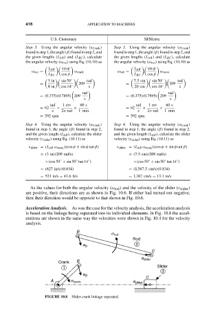
Acceleration Analysis. As was the case for the velocity analysis, the acceleration analysis
is based on the linkage being separated into its individual elements. In Fig. 10.8 the accel-
erations are shown in the same way the velocities were shown in Fig. 10.4 for the velocity
analysis.
B a rod
ìrodî
Rod
a B Ç 2
C
a slider
Crank B
1 Slider
3
a B
A a crank a slider C
FIGURE 10.8 Slider-crank linkage separated.