
Page 432 - Marks Calculation for Machine Design
P. 432
P2: Sanjay
P1: Shibu/Rakesh
January 4, 2005
15:34
Brown.cls
Brown˙C10
414
APPLICATION TO MACHINES
Solving for the angular velocity (ω rod ) in Eq. (10.6) gives
v B sin φ
ω rod = (10.7)
L BC cos β
Substituting the angular velocity (ω rod ) from Eq. (10.7) in Eq. (10.5) and simplifying
gives the velocity of the slider (v slider ) as
v B sin φ
v slider = v B cos φ + L BC sin β
L BC cos β
(10.8)
= v B cos φ + v B sin φ tan β
= v B (cos φ + sin φ tan β)
Similar to the expression for the velocity (v BC ) given by Eq. (10.2), the velocity (v B ) is
given by Eq. (10.9) as
v B = L AB ω crank (10.9)
Substituting for the velocity (v B ) from Eq. (10.9) in Eq. (10.7) gives
v B sin φ (L AB ω crank ) sin φ
ω rod = =
L BC cos β L BC cos β
(10.10)
L AB sin φ
= ω crank
L BC cos β
and substituting for the velocity (v B ) from Eq. (10.9) in Eq. (10.8) gives
v slider = v B (cos φ + sin φ tan β)
(10.11)
= (L AB ω crank )(cos φ + sin φ tan β)
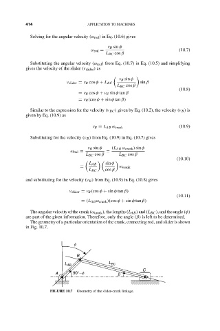
The angular velocity of the crank (ω crank ), the lengths (L AB ) and (L BC ), and the angle (φ)
are part of the given information. Therefore, only the angle (β) is left to be determined.
The geometry of a particular orientation of the crank, connecting rod, and slider is shown
in Fig. 10.7.
f
B
L AB L BC
C
A 90°- f b
FIGURE 10.7 Geometry of the slider-crank linkage.