
Page 428 - Marks Calculation for Machine Design
P. 428
P2: Sanjay
P1: Shibu/Rakesh
15:34
January 4, 2005
Brown.cls
Brown˙C10
APPLICATION TO MACHINES
410
10.2
LINKAGES
Linkages, also called mechanisms, transfer motion from one machine element to another.
They also transfer loads; however, it is the motion that is usually the mystery and once that
is understood the rest of the required design calculations become clear.
In Marks’ Standard Handbook for Mechanical Engineers the term mechanism is defined
as “that part of a machine which contains two or more pieces so arranged that the motion
of one compels the motion of the others, all in a fashion prescribed by the nature of the
combination.” This is a great definition. The keys words are compels, prescribed, and nature.
All the three of these key words describe not only the complexity of a mechanism, but also
its beauty and uniqueness.
There are three classic designs on which many variations are built: the four-bar linkage,
the quick-return linkage, and the slider-crank linkage. The combination of pieces in each of
these linkages is compelled to move in prescribed motions by the nature of the combination
as a consequence of the relative motion relationships that must exist between the pieces.
These relative motion relationships will be applied to the motion of the slider-crank linkage
presented later in this section.
10.2.1 Classic Designs
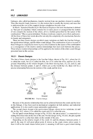
The first of three classic designs is the four-bar linkge, shown in Fig. 10.1, where bar (1)
is called the crank, bar (2) is called the link, bar (3) is called the lever, and bar (4) is the
ground. Depending on the relative lengths of the three moving bars, (1), (2), and (3), and
the distance between points A and D, which acts as the fourth bar (4), there will be a
precise relationship between the motion of the crank and the lever.
C
Link
B 2
Lever
3
Crank 1
Output
Input
A D
4
Ground
FIGURE 10.1 Four-bar linkage.
Because of the precise relationship that can be achieved between the crank and the lever
in this linkage, it has been used in mechanical computers in both military and industrial
applications. It is also used in many automotive applications.
The second classic design is the quick-return linkage, shown in two variations, (a) and
(b), in Fig. 10.2, where (1) is called the crank and (2) is called the arm.
For the quick-return linkage design in Fig. 10.2(a), the pin at point C is connected to a
sliding block that rides in the slot of the arm. For the design in Fig. 10.2(b), the pin at point
C is connected to a collar that slides on the outside of the arm.
Depending on the relative length of the crank (1) and the distance between points A
and B, the arm (2) will pivot about point B slower as the crank rotates above point A
than it will as the crank rotates below point A, meaning it will have a quick return during