
Page 430 - Marks Calculation for Machine Design
P. 430
P2: Sanjay
P1: Shibu/Rakesh
January 4, 2005
15:34
Brown.cls
Brown˙C10
412
APPLICATION TO MACHINES
10.2.2 Relative Motion
Consider the motion of the slider-crank linkage shown in Fig. 10.3, and assume the crank
(1) drives the slider (3). Therefore, the motion of the crank will be known completely, and
because it is in pure rotation about point A, this means only its angular velocity (ω crank )
and angular acceleration (α crank ) must be specified. Pure rotation means that every point
on this element of the linkage moves in a circle about the point A.
On the other hand, the motion of the slider (3) is constrained to move in pure translation
along the horizontal surface; however, the magnitude and direction (left or right) of its
velocity (v slider ) and acceleration (a slider ) will vary. Pure translation means every point on
this element of the linkage moves in a straight line.
Connecting the crank and slider is the connecting rod (2) which moves in general plane
motion, which is a combination of pure rotation and pure translation. Therefore, its angular
velocity (ω rod ) and angular acceleration (α rod ) will vary, depending on the relative lengths
of the crank (1) and connecting rod (2) and the given magnitude and direction (clockwise
or counterclockwise) of the angular velocity (ω crank ) and angular acceleration (α crank ) of
the crank.
Therefore, there are two unknowns associated with velocity: the velocity of the slider
(v slider ) and the angular velocity of the rod (ω rod ). Similarly, there are two unknowns associ-
ated with acceleration: the acceleration of the slider (a slider ) and the angular acceleration of
the rod (α rod ). To determine two unknowns, two equations are needed, one set for velocity
and the other set for acceleration. These equations are provided from the relative motion
relationships that must exist between the elements of the linkage.
Velocity Analysis. As the motion of even the simplest linkage is complex, the velocity
analysis begins by separating the linkage into its individual elements. This might be called
the “golden rule” of linkage analysis, that is, always separate the linkage into its individual
elements, each with its own unique motion.
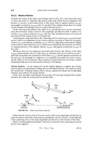
In Fig. 10.4, the slider-crank linkage shown in Fig. 10.3 has been separated into its three
elements: the crank, the connecting rod, and the slider.
B
w rod
Rod
2
v B
C v slider
Crank B
1 Slider
v B 3
C
A w crank v slider
FIGURE 10.4 Slider-crank linkage separated.
Notice that the velocity of point B on the crank is of the same magnitude and direction as
point B on the left end of the connecting rod, and that the velocity of point C on the right end
of the connecting rod is of the same magnitude and direction as the velocity of the slider.
There is a relationship between these velocities at each end of the connecting rod, given
by the vector equation
−→ −→ −→
v C = v B + v C/B (10.1)