
Page 429 - Marks Calculation for Machine Design
P. 429
P2: Sanjay
P1: Shibu/Rakesh
January 4, 2005
15:34
Brown.cls
Brown˙C10
MACHINE MOTION
Arm
2
2 Arm 411
Crank Crank
1 1
Input C Input C
A 3 A 3
Sliding block
Collar
Output Output
B B
(a) (b)
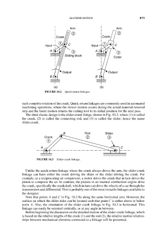
FIGURE 10.2 Quick-return linkages.
each complete rotation of the crank. Quick-return linkages are commonly used in automated
machining operations, where the slower motion occurs during the actual material removal
step and the faster motion returns the cutting tool to its initial position for the next pass.
The third classic design is the slider-crank linkge, shown in Fig. 10.3, where (1) is called
the crank, (2) is called the connecting rod, and (3) is called the slider; hence the name
slider-crank.
B Rod Slider
Crank 2 3
1
A C
FIGURE 10.3 Slider-crank linkage.
Unlike the quick-return linkage where the crank always drives the arm, the slider-crank
linkage can have either the crank driving the slider or the slider driving the crank. For
example, in a reciprocating air compressor, a motor drives the crank that in turn drives the
piston to compress the air. In contrast, the pistons in an internal combustion engine drive
the crank, specifically the crankshaft, which in turn can drive the wheels of a car through the
transmission and differential. This is probably one of the most versatile linkages available to
the designer.
Note that points A and C in Fig. 10.3 lie along the same horizontal axis. However, the
surface on which the slider rides can be located such that point C is either above or below
point A. Also, the orientation of the slider-crank linkage in Fig. 10.3 is horizontal. This
linkage can easily be oriented vertically, or at any angle in between.
Before beginning the discussion on the detailed motion of the slider-crank linkage, which
is based on the relative lengths of the crank (1) and the rod (2), the relative motion relation-
ships between mechanical elements connected to a linkage will be presented.