
Page 433 - Marks Calculation for Machine Design
P. 433
P2: Sanjay
P1: Shibu/Rakesh
January 4, 2005
15:34
Brown.cls
Brown˙C10
MACHINE MOTION
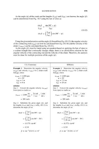
As the angle (φ) of the crank and the lengths (L AB ) and (L BC ) are known, the angle (β)
can be determined from Fig. 10.7 using the law of sines as 415
◦
sin β sin(90 − φ)
=
L AB L BC
(10.12)
L AB ◦
sin β = sin(90 − φ)
L BC
Usingthegiveninformationandtheangle(β)foundfromEq.(10.12),theangularvelocity
of the connecting rod (ω rod ) can now be calculated from Eq. (10.10) and the velocity of the
slider (v slider ) can be calculated from Eq. (10.11).
As the angle (β) must be found using an equation based on applying the law of sines to
a scalene triangle that continually changes shape, there is no closed-form solution for the
angular velocity of the connecting rod and the velocity of the slider. Therefore, the analysis
must be done for multiple positions of the angle (φ).
U.S. Customary SI/Metric
Example 1. Determine the angular velocity Example 1. Determine the angular velocity
(ω rod ) and velocity (v slider ) for a slider-crank (ω rod ) and velocity (v slider ) for a slider-crank
linkage, where linkage, where
ω crank = 2,000 rpm ω crank = 2,000 rpm
φ = 50 ◦ φ = 50 ◦
L AB = 3in L AB = 7.5 cm
L BC = 8in L BC = 20 cm
solution solution
Step 1. Convert the angular velocity (ω crank ) Step 1. Convert the angular velocity (ω crank )
from (rpm) to (rad/s) as from (rpm) to (rad/s) as
rev 2π rad 1 min rev 2π rad 1 min
ω crank = 2,000 × × ω crank = 2,000 × ×
min 1rev 60 s min 1rev 60 s
= 209 rad/s = 209 rad/s
Step 2. Substitute the given angle (φ), and Step 2. Substitute the given angle (φ), and
the lengths (L AB ) and (L BC ), in Eq. (10.11) to the lengths (L AB ) and (L BC ), in Eq. (10.11) to
determine the angle (β) as determine the angle (β) as
L AB ◦ L AB ◦
sin β = sin (90 − φ) sin β = sin (90 − φ)
L BC L BC
3in 7.5cm
◦
◦
◦
◦
= sin (90 − 50 ) = sin (90 − 50 )
8in 20 cm
= (0.375) sin 40 ◦ = (0.375) sin 40 ◦
= 0.241 = 0.241
β = sin −1 (0.241) = 14 ◦ β = sin −1 (0.241) = 14 ◦