
Page 101 - Mastering SolidWorks
P. 101
|
70 CHAPTER 3 Working With SketcheS and reference geometry
Figure 3.8
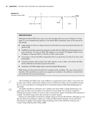
creating a sketch fillet
select
select lines result
Sketch Fillets
although the Sketch fillet tool is easy to use and may align with your way of working in a 2d pro-
gram, it is not considered best practice to use sketch fillets extensively. Some of the reasons for
this include:
◆ Large changes in the size or shape of the rest of the sketch can cause the feature built from the
sketch to fail.
◆ SolidWorks (and other parametric programs as well) often has difficulty solving tangent arcs in
some situations. you may see fillets flip tangency or go around 270 degrees instead of just
90 degrees. Using many fillets in a sketch can often cause trouble.
◆ if you want to remove the fillets temporarily, there is no good way to do this if you have used
sketch fillets.
◆ Sometimes feature order requires that other features, such as draft, come before the fillet,
which is difficult to do if they are part of the sketch.
◆ Sometimes a 2d fillet simply cannot create the required 3d geometry.
fillet features are the preferred method for creating rounds and fillets. the same can be said for
chamfers. Still, sometimes you need to use tangent arcs in sketches. you will have to decide which
way works best for you in each situation.
The Centerline tool follows the same methods as regular lines and is called a construction line
in some cases. Other construction entities, such as construction circles, are not available directly,
but you can create them by selecting the For Construction option in the PropertyManager for
any entity.
The Spline tool draws a freeform curve. Splines may form either a single closed loop or an
open loop. In either case, the spline is not allowed to cross itself. You can draw a spline by
clicking each location where you want to add a control point. Figure 3.9 identifies the elements of
a spline. The detail image shows the structure of a spline handle.
Splines are used mainly for freeform complex shapes in 2D and 3D sketches, although you can
also use them for anything in which you would use other sketch elements. If you need more
information on splines and complex shape modeling, refer to the SolidWorks Surfacing and
Complex Shape Modeling Bible (Wiley, 2008).