
Page 108 - Mastering SolidWorks
P. 108
|
identifying Sketch entitieS 77
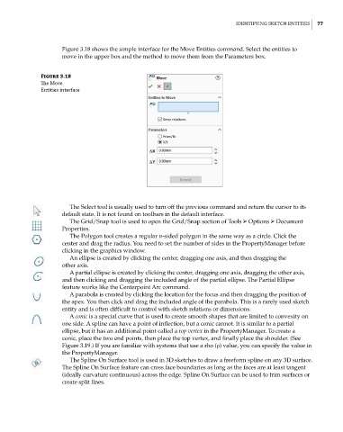
Figure 3.18 shows the simple interface for the Move Entities command. Select the entities to
move in the upper box and the method to move them from the Parameters box.
Figure 3.18
The move
entities interface
The Select tool is usually used to turn off the previous command and return the cursor to its
default state. It is not found on toolbars in the default interface.
The Grid/Snap tool is used to open the Grid/Snap section of Tools ➢ Options ➢ Document
Properties.
The Polygon tool creates a regular n-sided polygon in the same way as a circle. Click the
center and drag the radius. You need to set the number of sides in the PropertyManager before
clicking in the graphics window.
An ellipse is created by clicking the center, dragging one axis, and then dragging the
other axis.
A partial ellipse is created by clicking the center, dragging one axis, dragging the other axis,
and then clicking and dragging the included angle of the partial ellipse. The Partial Ellipse
feature works like the Centerpoint Arc command.
A parabola is created by clicking the location for the focus and then dragging the position of
the apex. You then click and drag the included angle of the parabola. This is a rarely used sketch
entity and is often difficult to control with sketch relations or dimensions.
A conic is a special curve that is used to create smooth shapes that are limited to convexity on
one side. A spline can have a point of inflection, but a conic cannot. It is similar to a partial
ellipse, but it has an additional point called a top vertex in the PropertyManager. To create a
conic, place the two end points, then place the top vertex, and finally place the shoulder. (See
Figure 3.19.) If you are familiar with systems that use a rho (ρ) value, you can specify the value in
the PropertyManager.
The Spline On Surface tool is used in 3D sketches to draw a freeform spline on any 3D surface.
The Spline On Surface feature can cross face boundaries as long as the faces are at least tangent
(ideally curvature continuous) across the edge. Spline On Surface can be used to trim surfaces or
create split lines.