
Page 168 - Mastering SolidWorks
P. 168
|
Creating a Simple drawing 137
4. Apply a last set of .050-inch chamfers to the backside of the counterbores and slot.
5. Save the part, as Chapter4SimpleMachinedPart and then close it.
The finished part is simple, but you have learned many useful techniques along the way.
Tutorial: Making a Simple Drawing
In SolidWorks, drawing views are created from the 3D model. Even the most complex section
views are almost free, because they are simply projected from the 3D model. When you make
changes to the 3D model, all 2D views update. You can handle dimensions in a couple of ways,
either using the dimensions that you used to create the model or placing new dimensions on the
drawing. (Best practice for modeling is not necessarily the same as best practice for manufactur-
ing drawings.) Model-Based Definition (MBD) is covered in Chapter 40, “Using Model-
Based Design.”
To make a simple drawing of a SolidWorks native part, follow these steps:
1. Click the New button from the standard toolbar, or choose File ➢ New. From the New
SolidWorks Document window, select the Blank Drawing template. The template contains
all the document-specific settings.
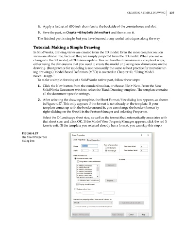
2. After selecting the drawing template, the Sheet Format/Size dialog box appears, as shown
in Figure 4.27. This only appears if the format is not already in the template. If your
template comes up with the border around it, you can change the border/format by
right-clicking on the Sheet1 in the FeatureManager and selecting Properties.
Select the D-Landscape sheet size, as well as the format that automatically associates with
that sheet size, and click OK. If the Model View PropertyManager appears, click the red X
icon to exit. (If the template you selected already has a format, you can skip this step.)
Figure 4.27
The Sheet properties
dialog box