
Page 171 - Mastering SolidWorks
P. 171
|
140 CHAPTER 4 Creating Simple partS and drawingS
14. Click the Section View button on the Drawings toolbar. This activates the Section View
Assist command so you can place a section line in a view. If you need a cutting line other
than a single straight line, the PropertyManager has some options, and other options will
be presented after you place the line to allow you to edit it.
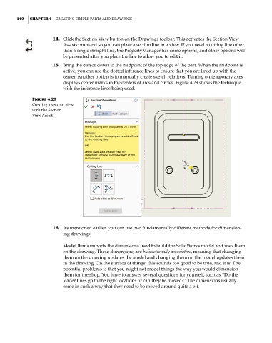
15. Bring the cursor down to the midpoint of the top edge of the part. When the midpoint is
active, you can use the dotted inference lines to ensure that you are lined up with the
center. Another option is to manually create sketch relations. Turning on temporary axes
displays center marks in the centers of arcs and circles. Figure 4.29 shows the technique
with the inference lines being used.
Figure 4.29
Creating a section view
with the Section
View assist
16. As mentioned earlier, you can use two fundamentally different methods for dimension-
ing drawings:
Model Items imports the dimensions used to build the SolidWorks model and uses them
on the drawing. These dimensions are bidirectionally associative, meaning that changing
them on the drawing updates the model and changing them on the model updates them
in the drawing. On the surface of things, this sounds too good to be true, and it is. The
potential problems is that you might not model things the way you would dimension
them for the shop. You have to answer several questions for yourself, such as “Do the
leader lines go to the right locations or can they be moved?” The dimensions usually
come in such a way that they need to be moved around quite a bit.