
Page 294 - Mastering SolidWorks
P. 294
|
266 CHAPTER 8 Selecting Secondary FeatureS
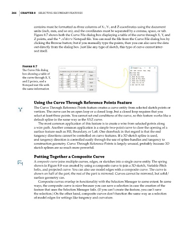
contains must be formatted as three columns of X-, Y-, and Z-coordinates using the document
units (inch, mm, and so on), and the coordinates must be separated by a comma, space, or tab.
Figure 8.7 shows both the Curve File dialog box displaying a table of the curve through X, Y, and
Z points, and the *.sldcrv Notepad file. You can read the file from the Curve File dialog box by
clicking the Browse button; but if you manually type the points, then you can also save the data
out directly from the dialog box. Just like any type of sketch, this type of curve cannot inter-
sect itself.
Figure 8.7
The curve File dialog
box showing a table of
the curve through X, y,
and Z points, and a
notepad text file with
the same information
Using the Curve Through Reference Points Feature
The Curve Through Reference Points feature creates a curve entity from selected sketch points or
vertices. The curve can be an open loop or a closed loop, but a closed loop requires that you
select at least three points. You cannot set end conditions of the curve, so this feature works like a
default spline in the same way as the XYZ curve.
The most common application of this feature is to create a wire from selected points along
a wire path. Another common application is a simple two-point curve to close the opening of a
surface feature such as Fill, Boundary, or Loft. One drawback in that regard is that the end
tangency directions cannot be controlled on curve features. If a 3D sketch spline is used,
end tangency direction is controlled easily through the use of spline handles and tangency to
construction geometry. Curve Through Reference Points is largely unused, probably because 3D
sketch splines are so much more powerful.
Putting Together a Composite Curve
A composite curve joins multiple curves, edges, or sketches into a single curve entity. The spring
shown in Figure 8.8 was created by using a composite curve to join a 3D sketch, Variable Pitch
helix, and projected curve. You can also use model edges with a composite curve. The curve is
shown on half of the part; the rest of the part is mirrored. Curves cannot be mirrored, but solid/
surface geometry can.
Composite curves overlap in functionality with the Selection Manager to some extent. In some
ways, the composite curve is nicer because you can save a selection in case the creation of the
feature that uses the Selection Manager fails. (If you can’t create the feature, you can’t save
the selection.) On the other hand, composite curves don’t function the same way as a selection
of model edges for settings like tangency and curvature.