
Page 293 - Mastering SolidWorks
P. 293
|
creating curve FeatureS 265
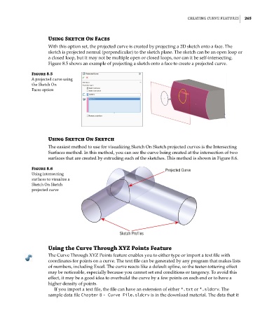
Using Sketch On Faces
With this option set, the projected curve is created by projecting a 2D sketch onto a face. The
sketch is projected normal (perpendicular) to the sketch plane. The sketch can be an open loop or
a closed loop, but it may not be multiple open or closed loops, nor can it be self-intersecting.
Figure 8.5 shows an example of projecting a sketch onto a face to create a projected curve.
Figure 8.5
a projected curve using
the Sketch on
Faces option
Using Sketch On Sketch
The easiest method to use for visualizing Sketch On Sketch projected curves is the Intersecting
Surfaces method. In this method, you can see the curve being created at the intersection of two
surfaces that are created by extruding each of the sketches. This method is shown in Figure 8.6.
Figure 8.6 Projected Curve
using intersecting
surfaces to visualize a
Sketch on Sketch
projected curve
Sketch Profiles
Using the Curve Through XYZ Points Feature
The Curve Through XYZ Points feature enables you to either type or import a text file with
coordinates for points on a curve. The text file can be generated by any program that makes lists
of numbers, including Excel. The curve reacts like a default spline, so the teeter-tottering effect
may be noticeable, especially because you cannot set end conditions or tangency. To avoid this
effect, it may be a good idea to overbuild the curve by a few points on each end or to have a
higher density of points.
If you import a text file, the file can have an extension of either *.txt or *.sldcrv. The
sample data file Chapter 8 - Curve File.sldcrv is in the download material. The data that it