
Page 309 - Mastering SolidWorks
P. 309
|
tutorial: creating a Wire-ForMed Part 281
6. Exit the sketch and create a projected curve. The Projected Curve function is found at
Insert ➢ Curve ➢ Projected Curve. Use the Sketch On Sketch option.
7. Open a 3D sketch. You can access a 3D sketch from the Insert menu. Select the helix and
click Convert Entities on the Sketch toolbar. Then select the projected curve, and click
Convert Entities again. You now have two sections of a 3D sketch that are not con-
nected in space.
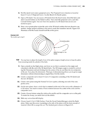
8. Draw a two-point spline to join the ends of the 3D sketch entities that are closest to one
another. Assign tangent relations to the ends to make the transition smooth. Figure 8.20
illustrates what the model should look like at this point.
Figure 8.20
The results up to step 8
Connecting spline
Adjust the length of this
handle
TIP you may have to adjust the length of one of the spline tangency length arrows to keep the spline
from remaining inside the cylinder of the helix.
9. Open a sketch on the Right plane, and draw an arc that is centered on the origin and
coincident with the end of the 3D sketch helix. The 185-degree angle is created by activat-
ing the Dimension tool and clicking first the center of the arc and then the two endpoints
of the arc. Now place the dimension. This type of dimensioning allows you to get an angle
dimension without dimensioning to angled lines. Exit the sketch.
10. Create a composite curve (Insert ➢ Curve ➢ Composite) consisting of the 3D sketch and
the new 2D sketch.
11. Create a new plane using the Normal To Curve option, selecting one end of the com-
posite curve.
12. On the new plane, draw a circle that is centered on the end of the curve with a diameter of
0.120 inches. You need to create a Pierce relation between the center of the circle and the
composite curve.
13. Create a Sweep feature using the circle as the profile and the composite curve as the path.
To create the sweep, you must first exit the sketch.
14. Hide any curves that still display.
15. Choose Insert ➢ Cut ➢ With Surface. From the flyout FeatureManager, select the Right
plane. Make sure the arrow is pointing to the side of the plane with the least amount of
material. Click OK to accept the cut. The finished part is shown in Figure 8.21.