
Page 308 - Mastering SolidWorks
P. 308
|
280 CHAPTER 8 Selecting Secondary FeatureS
Tutorial: Creating a Wire-Formed Part
Follow these steps to create a wire-formed part:
1. Open a new part using an inch-based template.
2. Open a sketch on the Right (or Side) plane, and sketch a circle that is centered on the
origin with a diameter of 1.500 inches.
3. Create a Helix, Constant Pitch, Pitch, and Revolution, where Pitch = .250 inches,
Revolutions = 5.15, and Start Angle = 0. The Helix command is found at Insert ➢ Curve ➢
Helix/Spiral.
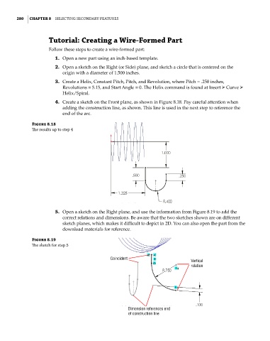
4. Create a sketch on the Front plane, as shown in Figure 8.18. Pay careful attention when
adding the construction line, as shown. This line is used in the next step to reference the
end of the arc.
Figure 8.18
The results up to step 4
5. Open a sketch on the Right plane, and use the information from Figure 8.19 to add the
correct relations and dimensions. Be aware that the two sketches shown are on different
sketch planes, which makes it difficult to depict in 2D. You can also open the part from the
download materials for reference.
Figure 8.19
The sketch for step 5
Coincident Vertical
relation
Dimension references end
of construction line