
Page 331 - Mastering SolidWorks
P. 331
|
UnderStAnding PAttern tYPeS 303
The X, Y origin for the table is determined by a Coordinate System Reference Geometry
feature. The XY plane of the coordinate system is the plane to which the XY data in the
table refers.
You can access the Coordinate System command by choosing Insert ➢ Reference Geometry ➢
Coordinate System from the menu. You can create the coordinate system by selecting a combina-
tion of a vertex for the origin and edges to align the axes. Like the Sketch Driven Pattern com-
mand, this feature can use either the centroid or a selected point on the feature to act as the
reference point.
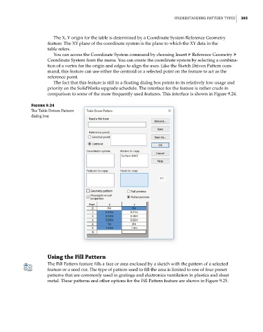
The fact that this feature is still in a floating dialog box points to its relatively low usage and
priority on the SolidWorks upgrade schedule. The interface for the feature is rather crude in
comparison to some of the more frequently used features. This interface is shown in Figure 9.24.
Figure 9.24
The table driven Pattern
dialog box
Using the Fill Pattern
The Fill Pattern feature fills a face or area enclosed by a sketch with the pattern of a selected
feature or a seed cut. The type of pattern used to fill the area is limited to one of four preset
patterns that are commonly used in gratings and electronics ventilation in plastics and sheet
metal. These patterns and other options for the Fill Pattern feature are shown in Figure 9.25.