
Page 333 - Mastering SolidWorks
P. 333
|
UnderStAnding PAttern tYPeS 305
As you might expect with anything so powerful, there are limitations. For example, it will not
allow you to pattern Hole Wizard holes or other patterns. Also, it will not accept a 3D sketch as
reference geometry. Being such a highly parametric feature, the Variable Pattern command tends
to be susceptible to some long-standing difficulties in SolidWorks, such as getting directions
confused when spinning an angle.
Most of the examples of this function you will see around the Internet are simplistic, 2D, and
don’t really capture its unique capabilities, nor do they offer any compelling reasons to use it. I
have two examples for you here. One is rather abstract and presented to show the concept. The
other shows a slightly more plausible application. The difficulty with spinning angles is the
reason most of the examples you see involve XY-grid sort of parametrics. You can get it to work,
but it may be easier to do a different way. Let’s start with a simple example.
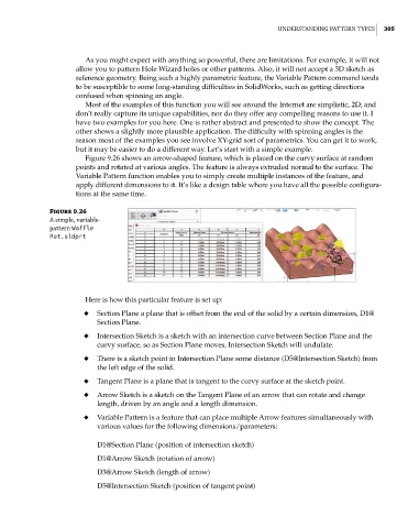
Figure 9.26 shows an arrow-shaped feature, which is placed on the curvy surface at random
points and rotated at various angles. The feature is always extruded normal to the surface. The
Variable Pattern function enables you to simply create multiple instances of the feature, and
apply different dimensions to it. It’s like a design table where you have all the possible configura-
tions at the same time.
Figure 9.26
A simple, variable-
pattern Waffle
Mat.sldprt
Here is how this particular feature is set up:
◆ Section Plane a plane that is offset from the end of the solid by a certain dimension, D1@
Section Plane.
◆ Intersection Sketch is a sketch with an intersection curve between Section Plane and the
curvy surface, so as Section Plane moves, Intersection Sketch will undulate.
◆ There is a sketch point in Intersection Plane some distance (D5@Intersection Sketch) from
the left edge of the solid.
◆ Tangent Plane is a plane that is tangent to the curvy surface at the sketch point.
◆ Arrow Sketch is a sketch on the Tangent Plane of an arrow that can rotate and change
length, driven by an angle and a length dimension.
◆ Variable Pattern is a feature that can place multiple Arrow features simultaneously with
various values for the following dimensions/parameters:
D1@Section Plane (position of intersection sketch)
D1@Arrow Sketch (rotation of arrow)
D3@Arrow Sketch (length of arrow)
D5@Intersection Sketch (position of tangent point)