
Page 345 - Mastering SolidWorks
P. 345
|
318 CHAPTER 10 USIng EqUATIOnS
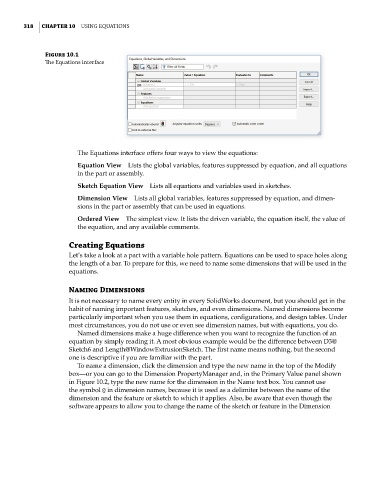
Figure 10.1
The Equations interface
The Equations interface offers four ways to view the equations:
Equation View Lists the global variables, features suppressed by equation, and all equations
in the part or assembly.
Sketch Equation View Lists all equations and variables used in sketches.
Dimension View Lists all global variables, features suppressed by equation, and dimen-
sions in the part or assembly that can be used in equations.
Ordered View The simplest view. It lists the driven variable, the equation itself, the value of
the equation, and any available comments.
Creating Equations
Let’s take a look at a part with a variable hole pattern. Equations can be used to space holes along
the length of a bar. To prepare for this, we need to name some dimensions that will be used in the
equations.
Naming Dimensions
It is not necessary to name every entity in every SolidWorks document, but you should get in the
habit of naming important features, sketches, and even dimensions. Named dimensions become
particularly important when you use them in equations, configurations, and design tables. Under
most circumstances, you do not use or even see dimension names, but with equations, you do.
Named dimensions make a huge difference when you want to recognize the function of an
equation by simply reading it. A most obvious example would be the difference between D3@
Sketch6 and Length@WindowExtrusionSketch. The first name means nothing, but the second
one is descriptive if you are familiar with the part.
To name a dimension, click the dimension and type the new name in the top of the Modify
box—or you can go to the Dimension PropertyManager and, in the Primary Value panel shown
in Figure 10.2, type the new name for the dimension in the Name text box. You cannot use
the symbol @ in dimension names, because it is used as a delimiter between the name of the
dimension and the feature or sketch to which it applies. Also, be aware that even though the
software appears to allow you to change the name of the sketch or feature in the Dimension