
Page 348 - Mastering SolidWorks
P. 348
|
UndErSTAndIng EqUATIOnS 321
TIP dimensions—and text in general—can be difficult to read when foreshortened on a 3d display.
To make text easier to read, there is a setting to show all dimensions flat to the screen; it can be found
at Tools ➢ Options ➢ display.
In this case, a more sophisticated equation has not been implemented to account for the
diameter of the holes possibly interfering with one another when there are a large number of
holes. In other words, because there are two values that need to be calculated (the spacing and
the gap), you need to create two equations. Because the gap dimension is always half of the
spacing, the spacing needs to be calculated first, as follows:
Length
Spacing =
Instances 1+1
The Instances –1 term stands for the number of spacings. If you have two holes, then there is
only one spacing. The +1 term stands for the two half-spacings for the two ends. The second
equation is simpler and looks like this:
Gap = Spacing
2
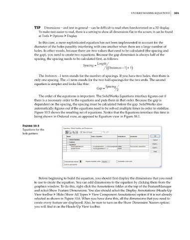
The order of the equations is important. The SolidWorks Equations interface figures out if
there is a necessary order to the equations and puts them in that order. Because the gap is
dependent on the spacing, the spacing must be calculated before the gap. SolidWorks also
automatically figures out if the equations need to be solved multiple times in order to stabilize.
Figure 10.5 shows the resulting set of equations. Notice that the Equations interface this time is
being shown in Ordered view, as opposed to Equation view in Figure 10.1.
Figure 10.5
Equations for the
hole pattern
Before beginning to build the equation, you should first display the dimensions that you need
to use to create the equation. You can add dimensions to the equation by clicking them from the
graphics window. To do this, right-click the Annotations folder at the top of the FeatureManager
and select Show Feature Dimensions. You also should select the Display Annotations (Heads-Up
View toolbar ➢ Hide/Show All Types ➢ View Component Annotations) option if it is not already
selected as shown in Figure 10.6. When you have done this, all the dimensions that you need to
create every feature are displayed. Also, be sure to turn on the Show Dimension Names option;
you will find it on the Heads-Up View toolbar.