
Page 350 - Mastering SolidWorks
P. 350
|
UndErSTAndIng EqUATIOnS 323
Using Comments
Notice the comment to the right of the Evaluates To column in Figure 10.5. Comments can be
very useful for annotating equations for yourself or others. Two important reasons to annotate
are to remember the significance of variables or dimensions and to add special notes about the
logic of the equation that may not be obvious.
TIP You can make general comments for the model in the design Journal, a Microsoft Word docu-
ment that is embedded into the SolidWorks file. The design Journal is found in the design Binder
folder near the top of the FeatureManager.
Using Driven Dimensions
Sometimes it is necessary to use a driven (reference) dimension in an equation. Reference
dimensions are displayed in gray. This is particularly true when the best way to calculate a
number is to use existing 3D geometry. For example, if you are manufacturing a helical auger in
90-degree sections from flat steel stock, you need to design the auger in 3D but begin to manufac-
ture it in 2D.
What is the shape of the auger when flat? The best way to figure this out (aside from lofted
bends, which are discussed in Chapter 34, “Using SolidWorks Sheet Metal Tools”) is to use a little
high-school geometry, a construction sketch, and some simple equations.
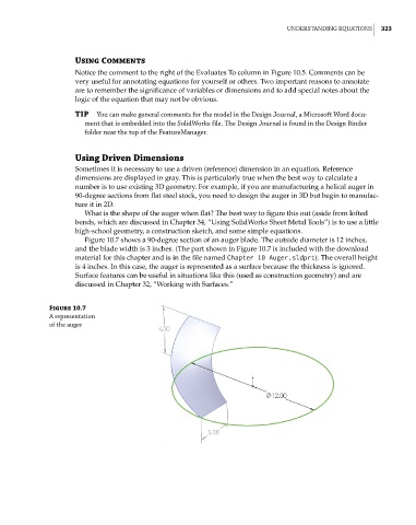
Figure 10.7 shows a 90-degree section of an auger blade. The outside diameter is 12 inches,
and the blade width is 3 inches. (The part shown in Figure 10.7 is included with the download
material for this chapter and is in the file named Chapter 10 Auger.sldprt). The overall height
is 4 inches. In this case, the auger is represented as a surface because the thickness is ignored.
Surface features can be useful in situations like this (used as construction geometry) and are
discussed in Chapter 32, “Working with Surfaces.”
Figure 10.7
A representation
of the auger