
Page 351 - Mastering SolidWorks
P. 351
|
324 CHAPTER 10 USIng EqUATIOnS
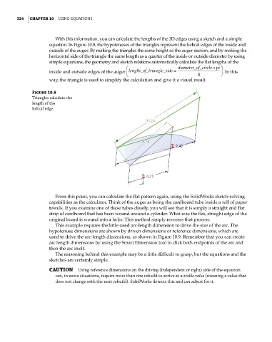
With this information, you can calculate the lengths of the 3D edges using a sketch and a simple
equation. In Figure 10.8, the hypotenuses of the triangles represent the helical edges of the inside and
outside of the auger. By making the triangles the same height as the auger section, and by making the
horizontal side of the triangle the same length as a quarter of the inside or outside diameter by using
simple equations, the geometry and sketch relations automatically calculate the flat lengths of the
diameter_of_circlepi
inside and outside edges of the auger length_of_triangle_side= . In this
4
way, the triangle is used to simplify the calculation and give it a visual result.
Figure 10.8
Triangles calculate the
length of the
helical edge.
From this point, you can calculate the flat pattern again, using the SolidWorks sketch-solving
capabilities as the calculator. Think of the auger as being the cardboard tube inside a roll of paper
towels. If you examine one of these tubes closely, you will see that it is simply a straight and flat
strip of cardboard that has been wound around a cylinder. What was the flat, straight edge of the
original board is wound into a helix. This method simply reverses that process.
This example requires the little-used arc-length dimension to drive the size of the arc. The
hypotenuse dimensions are shown by driven dimensions or reference dimensions, which are
used to drive the arc-length dimensions, as shown in Figure 10.9. Remember that you can create
arc length dimensions by using the Smart Dimension tool to click both endpoints of the arc and
then the arc itself.
The reasoning behind this example may be a little difficult to grasp, but the equations and the
sketches are certainly simple.
CAUTION Using reference dimensions on the driving (independent or right) side of the equation
can, in some situations, require more than one rebuild to arrive at a stable value (meaning a value that
does not change with the next rebuild). SolidWorks detects this and can adjust for it.