
Page 110 - Materials Science and Engineering An Introduction
P. 110
82 • Chapter 3 / The Structure of Crystalline Solids
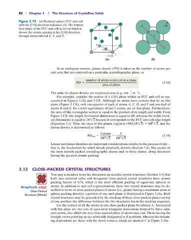
Figure 3.15 (a) Reduced-sphere FCC unit cell
with the [110] direction indicated. (b) The bottom X R
face-plane of the FCC unit cell in (a) on which is
shown the atomic spacing in the [110] direction,
through atoms labeled X, Y, and Z. Y
X
Z
Y
Z
[110]
(a) (b)
In an analogous manner, planar density (PD) is taken as the number of atoms per
unit area that are centered on a particular crystallographic plane, or
number of atoms centered on a plane
PD = (3.18)
area of plane
2
2
The units for planar density are reciprocal area (e.g., nm , m ).
For example, consider the section of a (110) plane within an FCC unit cell as rep-
resented in Figures 3.12a and 3.12b. Although six atoms have centers that lie on this
plane (Figure 3.12b), only one-quarter of each of atoms A, C, D, and F and one-half of
atoms B and E, for a total equivalence of just 2 atoms, are on that plane. Furthermore,
the area of this rectangular section is equal to the product of its length and width. From
Figure 3.12b, the length (horizontal dimension) is equal to 4R, whereas the width (verti-
cal dimension) is equal to 2R12 because it corresponds to the FCC unit cell edge length
(Equation 3.1). Thus, the area of this planar region is (4R)(2R12) = 8R 12, and the
2
planar density is determined as follows:
2 atoms 1
PD 110 = = (3.19)
2
2
8R 12 4R 12
Linear and planar densities are important considerations relative to the process of slip—
that is, the mechanism by which metals plastically deform (Section 7.4). Slip occurs on
the most densely packed crystallographic planes and, in those planes, along directions
having the greatest atomic packing.
3.12 CLOSE-PACKED CRYSTAL STRUCTURES
You may remember from the discussion on metallic crystal structures (Section 3.4) that
both face-centered cubic and hexagonal close-packed crystal structures have atomic
packing factors of 0.74, which is the most efficient packing of equal-size spheres or
atoms. In addition to unit cell representations, these two crystal structures may be de-
: VMSE
Close-Packed scribed in terms of close-packed planes of atoms (i.e., planes having a maximum atom or
Structures (Metals) sphere-packing density); a portion of one such plane is illustrated in Figure 3.16a. Both
crystal structures may be generated by the stacking of these close-packed planes on top
of one another; the difference between the two structures lies in the stacking sequence.
Let the centers of all the atoms in one close-packed plane be labeled A. Associated
with this plane are two sets of equivalent triangular depressions formed by three adja-
cent atoms, into which the next close-packed plane of atoms may rest. Those having the
triangle vertex pointing up are arbitrarily designated as B positions, whereas the remain-
ing depressions are those with the down vertices, which are marked C in Figure 3.16a.