
Page 109 - Materials Science and Engineering An Introduction
P. 109
3.11 Linear and Planar Densities • 81
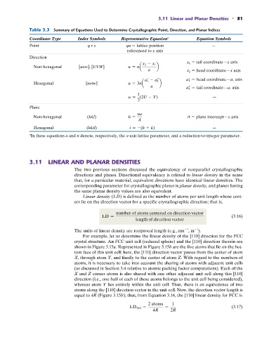
Table 3.3 Summary of Equations Used to Determine Crystallographic Point, Direction, and Planar Indices
Coordinate Type Index Symbols Representative Equation a Equation Symbols
Point q r s qa lattice position —
referenced to x axis
Direction
x 1 tail coordinate—x axis
Non-hexagonal [uyw], [UVW] u = na x 2 - x 1 b
a x 2 head coordinate—x axis
a 1 = head coordinate—a 1 axis
Hexagonal [uytw] u = 3na a 1 - a 1 b
a a 1 = tail coordinate—a 1 axis
1
u = (2U - V) —
3
Plane
na
Non-hexagonal (hkl) h = A plane intercept—x axis
A
Hexagonal (hkil) i = -(h + k) —
In these equations a and n denote, respectively, the x-axis lattice parameter, and a reduction-to-integer parameter.
a
3.11 LINEAR AND PLANAR DENSITIES
The two previous sections discussed the equivalency of nonparallel crystallographic
directions and planes. Directional equivalency is related to linear density in the sense
that, for a particular material, equivalent directions have identical linear densities. The
corresponding parameter for crystallographic planes is planar density, and planes having
the same planar density values are also equivalent.
Linear density (LD) is defined as the number of atoms per unit length whose cent-
ers lie on the direction vector for a specific crystallographic direction; that is,
number of atoms centered on direction vector
LD = (3.16)
length of direction vector
1
1
The units of linear density are reciprocal length (e.g., nm , m ).
For example, let us determine the linear density of the [110] direction for the FCC
crystal structure. An FCC unit cell (reduced sphere) and the [110] direction therein are
shown in Figure 3.15a. Represented in Figure 3.15b are the five atoms that lie on the bot-
tom face of this unit cell; here, the [110] direction vector passes from the center of atom
X, through atom Y, and finally to the center of atom Z. With regard to the numbers of
atoms, it is necessary to take into account the sharing of atoms with adjacent unit cells
(as discussed in Section 3.4 relative to atomic packing factor computations). Each of the
X and Z corner atoms is also shared with one other adjacent unit cell along this [110]
direction (i.e., one-half of each of these atoms belongs to the unit cell being considered),
whereas atom Y lies entirely within the unit cell. Thus, there is an equivalence of two
atoms along the [110] direction vector in the unit cell. Now, the direction vector length is
equal to 4R (Figure 3.15b); thus, from Equation 3.16, the [110] linear density for FCC is
2 atoms 1
LD 110 = = (3.17)
4R 2R