
Page 318 - Materials Science and Engineering An Introduction
P. 318
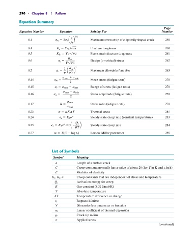
290   •  Chapter 8  /  Failure

            Equation Summary

                                                                                                  Page
            Equation Number         Equation          Solving For                               Number

                                           a  1/2
                  8.1             s m = 2s 0  a  b    Maximum stress at tip of elliptically shaped crack   258
                                           r t
                  8.4             K c = Ys c 1pa      Fracture toughness                          260
                  8.5             K Ic = Ys1pa        Plane-strain fracture toughness             261

                  8.6              s c =  K Ic        Design (or critical) stress                 262
                                        Y1pa
                                       1  K Ic  2
                  8.7             a c =   a  b        Maximum allowable flaw size                 263
                                       p  sY
                                      s max + s min
                  8.14           s m =                Mean stress (fatigue tests)                 270
                                          2
                  8.15           s r = s max - s min    Range of stress (fatigue tests)           270

                                      s max - s min
                  8.16           s a =                Stress amplitude (fatigue tests)            270
                                          2
                  8.17              R =  s min        Stress ratio (fatigue tests)                270
                                         s max
                  8.23             s = a l E  T       Thermal stress                              281
                                     #
                  8.24              P s = K 1 s       Steady-state creep rate (constant temperature)   283
                                            n
                                #
                                       n
                  8.25         P s = K 2 s expa -  Q c  b   Steady-state creep rate               284
                                             RT
                  8.27           m = T(C + log t r )  Larson–Miller parameter                     285


                                List of Symbols

                                Symbol        Meaning
                                              Length of a surface crack
                                  a
                                  C           Creep constant; normally has a value of about 20 (for T in K and t r  in h)
                                  E           Modulus of elasticity
                                  K 1 , K 2 , n   Creep constants that are independent of stress and temperature
                                 Q c          Activation energy for creep
                                                                  #
                                  R           Gas constant (8.31 J/mol K)
                                  T           Absolute temperature
                                  T           Temperature difference or change
                                              Rupture lifetime
                                  t r
                                  Y           Dimensionless parameter or function
                                  a l         Linear coefficient of thermal expansion
                                  r t         Crack tip radius
                                  s           Applied stress
                                                                                               (continued)