
Page 315 - Materials Science and Engineering An Introduction
P. 315
Summary • 287
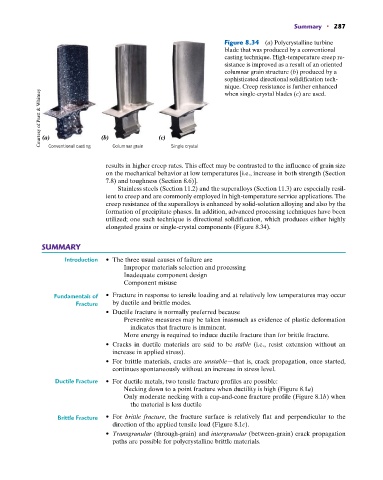
Figure 8.34 (a) Polycrystalline turbine
blade that was produced by a conventional
casting technique. High-temperature creep re-
sistance is improved as a result of an oriented
columnar grain structure (b) produced by a
sophisticated directional solidification tech-
nique. Creep resistance is further enhanced
Courtesy of Pratt & Whitney (a) (b) (c)
when single-crystal blades (c) are used.
Columnar grain
Conventional casting
Single crystal
results in higher creep rates. This effect may be contrasted to the influence of grain size
on the mechanical behavior at low temperatures [i.e., increase in both strength (Section
7.8) and toughness (Section 8.6)].
Stainless steels (Section 11.2) and the superalloys (Section 11.3) are especially resil-
ient to creep and are commonly employed in high-temperature service applications. The
creep resistance of the superalloys is enhanced by solid-solution alloying and also by the
formation of precipitate phases. In addition, advanced processing techniques have been
utilized; one such technique is directional solidification, which produces either highly
elongated grains or single-crystal components (Figure 8.34).
SUMMARY
Introduction • The three usual causes of failure are
Improper materials selection and processing
Inadequate component design
Component misuse
Fundamentals of • Fracture in response to tensile loading and at relatively low temperatures may occur
Fracture by ductile and brittle modes.
• Ductile fracture is normally preferred because
Preventive measures may be taken inasmuch as evidence of plastic deformation
indicates that fracture is imminent.
More energy is required to induce ductile fracture than for brittle fracture.
• Cracks in ductile materials are said to be stable (i.e., resist extension without an
increase in applied stress).
• For brittle materials, cracks are unstable—that is, crack propagation, once started,
continues spontaneously without an increase in stress level.
Ductile Fracture • For ductile metals, two tensile fracture profiles are possible:
Necking down to a point fracture when ductility is high (Figure 8.1a)
Only moderate necking with a cup-and-cone fracture profile (Figure 8.1b) when
the material is less ductile
Brittle Fracture • For brittle fracture, the fracture surface is relatively flat and perpendicular to the
direction of the applied tensile load (Figure 8.1c).
• Transgranular (through-grain) and intergranular (between-grain) crack propagation
paths are possible for polycrystalline brittle materials.