
Page 79 - Materials Science and Engineering An Introduction
P. 79
3 The Structure of
C h a p t e r
Crystalline Solids
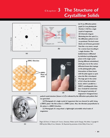
(a) X-ray diffraction photo-
graph [or Laue photograph
Diffracted
beams (Section 3.16)] for a single
Incident crystal of magnesium.
beam
(b) Schematic diagram
illustrating how the spots (i.e.,
Courtesy of J. G. Byrne Photographic plate Lead screen are produced. The lead screen
Single crystal
X-ray source
the diffraction pattern) in (a)
blocks out all beams generated
from the x-ray source, except
(b)
for a narrow beam traveling in
a single direction. This
(a) incident beam is diffracted
by individual crystallographic
planes in the single crystal
(having different orientations),
which gives rise to the various
diffracted beams that impinge
on the photographic plate.
Intersections of these beams
with the plate appear as spots
when the film is developed.
© William D. Callister, Jr. The large spot in the center
of (a) is from the incident
beam, which is parallel to a
[0001] crystallographic direc-
tion. It should be noted that
the hexagonal symmetry of
(c) (d) magnesium’s hexagonal close-
packed crystal structure [shown in (c)] is indicated by the diffraction spot pattern that
was generated.
(d) Photograph of a single crystal of magnesium that was cleaved (or split) along
a (0001) plane—the flat surface is a (0001) plane. Also, the direction perpendicular to
this plane is a [0001] direction.
(e) Photograph of a mag wheel—a lightweight automobile wheel made of
magnesium.
iStockphoto
(e) [Figure (b) from J. E. Brady and F. Senese, Chemistry: Matter and Its Changes, 4th edition. Copyright ©
2004 by John Wiley & Sons, Hoboken, NJ. Reprinted by permission of John Wiley & Sons, Inc.]
• 51