
Page 98 - Materials Science and Engineering An Introduction
P. 98
70 • Chapter 3 / The Structure of Crystalline Solids
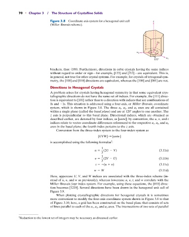
Figure 3.8 Coordinate axis system for a hexagonal unit cell z
(Miller–Bravais scheme).
a 2
a 3
a
120° 1
brackets, thus: 100 . Furthermore, directions in cubic crystals having the same indices
without regard to order or sign—for example, [123] and [213]—are equivalent. This is,
in general, not true for other crystal systems. For example, for crystals of tetragonal sym-
metry, the [100] and [010] directions are equivalent, whereas the [100] and [001] are not.
Directions in Hexagonal Crystals
A problem arises for crystals having hexagonal symmetry in that some equivalent crys-
tallographic directions do not have the same set of indices. For example, the [111] direc-
tion is equivalent to [101] rather than to a direction with indices that are combinations of
1s and 1s. This situation is addressed using a four-axis, or Miller–Bravais, coordinate
axes are all contained
system, which is shown in Figure 3.8. The three a 1 , a 2 , and a 3
within a single plane (called the basal plane) and are at 120 angles to one another. The
z axis is perpendicular to this basal plane. Directional indices, which are obtained as
described earlier, are denoted by four indices, as [uytw]; by convention, the u, y, and t
indices relate to vector coordinate differences referenced to the respective a 1 , a 2 , and a 3
axes in the basal plane; the fourth index pertains to the z axis.
Conversion from the three-index system to the four-index system as
[UVW] S [uytw]
5
is accomplished using the following formulas :
1
u = (2U - V) (3.11a)
3
1
y = (2V - U) (3.11b)
3
t = -(u + y) (3.11c)
w = W (3.11d)
Here, uppercase U, V, and W indices are associated with the three-index scheme (in-
stead of u, y, and w as previously), whereas lowercase u, y, t, and w correlate with the
Miller–Bravais four-index system. For example, using these equations, the [010] direc-
tion becomes [1210]. Several directions have been drawn in the hexagonal unit cell of
Figure 3.9.
When plotting crystallographic directions for hexagonal crystals it is sometimes
more convenient to modify the four-axis coordinate system shown in Figure 3.8 to that
of Figure 3.10; here, a grid has been constructed on the basal plane that consists of sets
of lines parallel to each of the a 1 , a 2 , and a 3 axes. The intersections of two sets of parallel
5 Reduction to the lowest set of integers may be necessary, as discussed earlier.