
Page 95 - Materials Science and Engineering An Introduction
P. 95
3.9 Crystallographic Directions • 67
3.9 CRYSTALLOGRAPHIC DIRECTIONS
A crystallographic direction is defined as a line directed between two points, or a vector.
The following steps are used to determine the three directional indices:
1. A right-handed x-y-z coordinate system is first constructed. As a matter of con-
: VMSE venience, its origin may be located at a unit cell corner.
Crystallographic 2. The coordinates of two points that lie on the direction vector (referenced to the
Directions coordinate system) are determined—for example, for the vector tail, point 1: x 1 ,
y 1 , and z 1 ; whereas for the vector head, point 2: x 2 , y 2 , and z 2 .
3. Tail point coordinates are subtracted from head point components—that is,
x 2 x 1 , y 2 y 1 , and z 2 z 1 .
Tutorial Video:
Crystallographic 4. These coordinate differences are then normalized in terms of (i.e., divided by)
Planes and their respective a, b, and c lattice parameters—that is,
Directions x 2 - x 1 y 2 - y 1 z 2 - z 1
a b c
which yields a set of three numbers.
5. If necessary, these three numbers are multiplied or divided by a common factor to
reduce them to the smallest integer values.
6. The three resulting indices, not separated by commas, are enclosed in square
brackets, thus: [uvw]. The u, v, and w integers correspond to the normalized
coordinate differences referenced to the x, y, and z axes, respectively.
In summary, the u, v, and w indices may be determined using the following equations:
x 2 - x 1
u = na b (3.10a)
a
v = na y 2 - y 1 b (3.10b)
b
w = na z 2 - z 1 b (3.10c)
c
In these expressions, n is the factor that may be required to reduce u, v, and w to integers.
For each of the three axes, there are both positive and negative coordinates. Thus,
negative indices are also possible, which are represented by a bar over the appropri-
ate index. For example, the [111] direction has a component in the y direction. Also,
changing the signs of all indices produces an antiparallel direction; that is, [111] is di-
rectly opposite to [111]. If more than one direction (or plane) is to be specified for a
particular crystal structure, it is imperative for maintaining consistency that a positive–
negative convention, once established, not be changed.
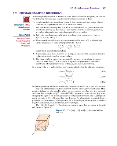
The [100], [110], and [111] directions are common ones; they are drawn in the unit
cell shown in Figure 3.7.
z Figure 3.7 The [100], [110], and [111] directions within a
unit cell.
[111]
y
[110]
[100]
x