
Page 92 - Materials Science and Engineering An Introduction
P. 92
64 • Chapter 3 / The Structure of Crystalline Solids
Crystallographic Points,
Directions, and Planes
When dealing with crystalline materials, it often becomes necessary to specify a particu-
lar point within a unit cell, a crystallographic direction, or some crystallographic plane
of atoms. Labeling conventions have been established in which three numbers or indices
are used to designate point locations, directions, and planes. The basis for determining
index values is the unit cell, with a right-handed coordinate system consisting of three
(x, y, and z) axes situated at one of the corners and coinciding with the unit cell edges,
as shown in Figure 3.5. For some crystal systems—namely, hexagonal, rhombohedral,
monoclinic, and triclinic—the three axes are not mutually perpendicular, as in the famil-
iar Cartesian coordinate scheme.
3.8 POINT COORDINATES
Sometimes it is necessary to specify a lattice position within a unit cell. This is possible
using three point coordinate indices: q, r, and s. These indices are fractional multiples of
a, b, and c unit cell edge lengths—that is, q is some fractional length of a along the x axis,
r is some fractional length of b along the y axis, and similarly for s; or
qa = lattice position referenced to the x axis (3.9a)
rb = lattice position referenced to the y axis (3.9b)
sc = lattice position referenced to the z axis (3.9c)
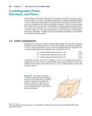
To illustrate, consider the unit cell in Figure 3.6, the x-y-z coordinate system with its
origin located at a unit cell corner, and the lattice site located at point P. Note how the
location of P is related to the products of its q, r, and s coordinate indices and the unit
cell edge lengths. 3
Figure 3.6 The manner in which the z
q, r, and s coordinates at point P within the
unit cell are determined. The q coordinate b
(which is a fraction) corresponds to the a
distance qa along the x axis, where a is
the unit cell edge length. The respective
r and s coordinates for the y and z axes are
determined similarly. P q r s
c
sc
y
qa
rb
x
3 We have chosen not to separate the q, r, and s indices by commas or any other punctuation marks (which is the
normal convention).