
Page 90 - Materials Science and Engineering An Introduction
P. 90
62 • Chapter 3 / The Structure of Crystalline Solids
3.7 CRYSTAL SYSTEMS
Because there are many different possible crystal structures, it is sometimes conven-
ient to divide them into groups according to unit cell configurations and/or atomic
arrangements. One such scheme is based on the unit cell geometry, that is, the shape
of the appropriate unit cell parallelepiped without regard to the atomic positions
: VMSE
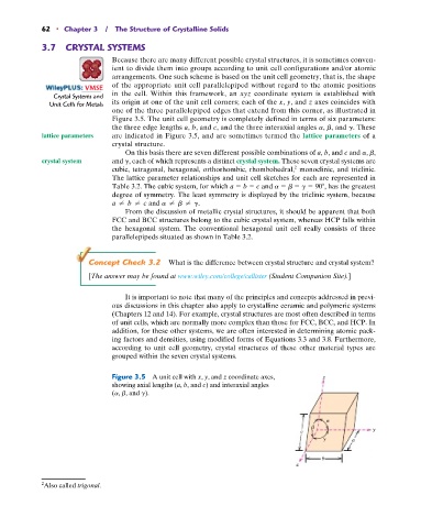
Crystal Systems and in the cell. Within this framework, an xyz coordinate system is established with
Unit Cells for Metals its origin at one of the unit cell corners; each of the x, y, and z axes coincides with
one of the three parallelepiped edges that extend from this corner, as illustrated in
Figure 3.5. The unit cell geometry is completely defined in terms of six parameters:
the three edge lengths a, b, and c, and the three interaxial angles a, b, and g. These
lattice parameters are indicated in Figure 3.5, and are sometimes termed the lattice parameters of a
crystal structure.
On this basis there are seven different possible combinations of a, b, and c and a, b,
crystal system and g, each of which represents a distinct crystal system. These seven crystal systems are
cubic, tetragonal, hexagonal, orthorhombic, rhombohedral, 2 monoclinic, and triclinic.
The lattice parameter relationships and unit cell sketches for each are represented in
Table 3.2. The cubic system, for which a b c and a b g 90 , has the greatest
degree of symmetry. The least symmetry is displayed by the triclinic system, because
a b c and a b g.
From the discussion of metallic crystal structures, it should be apparent that both
FCC and BCC structures belong to the cubic crystal system, whereas HCP falls within
the hexagonal system. The conventional hexagonal unit cell really consists of three
parallelepipeds situated as shown in Table 3.2.
Concept Check 3.2 What is the difference between crystal structure and crystal system?
[The answer may be found at www.wiley.com/college/callister (Student Companion Site).]
It is important to note that many of the principles and concepts addressed in previ-
ous discussions in this chapter also apply to crystalline ceramic and polymeric systems
(Chapters 12 and 14). For example, crystal structures are most often described in terms
of unit cells, which are normally more complex than those for FCC, BCC, and HCP. In
addition, for these other systems, we are often interested in determining atomic pack-
ing factors and densities, using modified forms of Equations 3.3 and 3.8. Furthermore,
according to unit cell geometry, crystal structures of these other material types are
grouped within the seven crystal systems.
Figure 3.5 A unit cell with x, y, and z coordinate axes, z
showing axial lengths (a, b, and c) and interaxial angles
(a, b, and g).
c y
a
b
x
2 Also called trigonal.