
Page 99 - Materials Science and Engineering An Introduction
P. 99
3.9 Crystallographic Directions • 71
z
z
[0001]
n
m
a 2 a 2
a 3 [1120] a 3
a 1
[1100]
a 1
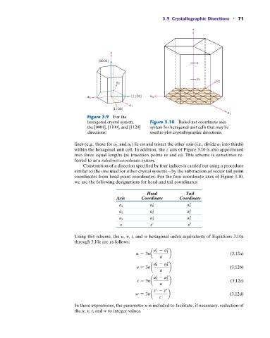
Figure 3.9 For the
hexagonal crystal system, Figure 3.10 Ruled-net coordinate axis
the [0001], [1100], and [1120] system for hexagonal unit cells that may be
directions. used to plot crystallographic directions.
lines (e.g., those for a 2 , and a 3 ) lie on and trisect the other axis (i.e., divide a 1 into thirds)
within the hexagonal unit cell. In addition, the z axis of Figure 3.10 is also apportioned
into three equal lengths (at trisection points m and n). This scheme is sometimes re-
ferred to as a ruled-net coordinate system.
Construction of a direction specified by four indices is carried out using a procedure
similar to the one used for other crystal systems—by the subtraction of vector tail point
coordinates from head point coordinates. For the four coordinate axes of Figure 3.10,
we use the following designations for head and tail coordinates:
Head Tail
Axis Coordinate Coordinate
a 1 a 1 a 1
a 2 a 2 a 2
a 3 a 3 a 3
z z z
Using this scheme, the u, y, t, and w hexagonal index equivalents of Equations 3.10a
through 3.10c are as follows:
a 1 - a 1
u = 3na b (3.12a)
a
a 2 - a 2
y = 3na b (3.12b)
a
a 3 - a 3
t = 3na b (3.12c)
a
z - z
w = 3na b (3.12d)
c
In these expressions, the parameter n is included to facilitate, if necessary, reduction of
the u, y, t, and w to integer values.