
Page 127 - Mathematical Models and Algorithms for Power System Optimization
P. 127
New Algorithms Related to Power Flow 117
At the fifth and sixth iterations: To reduce the maximum infeasibility (nonlinear), the bound S is
reduced to 0.025 and 0.00125. The objective function is no longer reduced, and the maximum
infeasibility is within the allowable range, so the calculation terminates.
From case 1 to case 4, the same bound adjustment method is used at Step 4. That is, bound S for
continuous variables is decreased by setting S¼S/2, and bound E is always set as 1. Although
there are a variety of methods to adjust the bounds S and E, the convergence properties are
almost the same according to our experience.
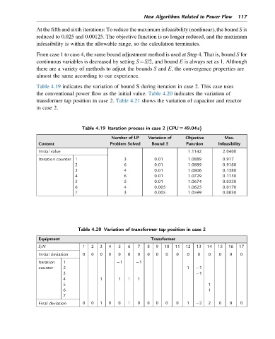
Table 4.19 indicates the variation of bound S during iteration in case 2. This case uses
the conventional power flow as the initial value. Table 4.20 indicates the variation of
transformer tap position in case 2. Table 4.21 shows the variation of capacitor and reactor
in case 2.
Table 4.19 Iteration process in case 2 (CPU549.04s)
Number of LP Variation of Objective Max.
Content Problem Solved Bound S Function Infeasibility
Initial value 1.1142 2.0400
Iteration counter 1 3 0.01 1.0889 0.917
2 6 0.01 1.0889 0.9180
3 4 0.01 1.0806 0.1580
4 6 0.01 1.0729 0.1150
5 5 0.01 1.0674 0.0330
6 4 0.005 1.0625 0.0170
7 3 0.005 1.0599 0.0030
Table 4.20 Variation of transformer tap position in case 2
Equipment Transformer
S/N 1 2 3 4 5 6 7 8 9 10 11 12 13 14 15 16 17
Initial deviation 0 0 0 0 0 0 0 0 0 0 0 0 0 0 0 0 0
Iteration 1 1 1
counter 2 1 1
3 1
4 1 1 1 1
5 1
6 1
7
Final deviation 0 0 1 0 0 1 0 0 0 0 0 1 2 2 0 0 0