
Page 206 - Mathematical Models and Algorithms for Power System Optimization
P. 206
Discrete Optimization for Reactive Power Planning 197
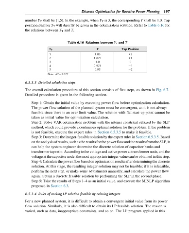
number Y T shall be [1,5]. In the example, when Y T is 3, the corresponding T shall be 1.0. Tap
position number Y T will directly be given in the optimization solution. Refer to Table 6.16 for
the relations between Y T and T.
Table 6.16 Relations between Y T and T
Y T T Tap Position
1 1.05 +2
2 1.025 +1
3 1.0 0
4 0.975 1
5 0.95 2
Note: ΔT¼0.025.
6.5.3.3 Detailed calculation steps
The overall calculation procedure of this section consists of five steps, as shown in Fig. 6.7.
Detailed procedure is given in the following section.
Step 1: Obtain the initial value by executing power flow before optimization calculation.
The power flow solution of the planned system must be convergent, as it is not always
feasible since there is an over limit value. The solution with flat start-up point cannot be
taken as initial value for optimization calculation.
Step 2: Solve VAR optimization problem with the integer constraint relaxed by the SLP
method, which could provide a continuous optimal solution for the problem. If the problem
is not feasible, execute the expert rules in Section 6.5.3.5 to make it feasible.
Step 3: Determine the integer-feasible solution by the expert rules in Section 6.5.3.5. Based
ontheanalysisofresults,suchastheresultsforthepowerflowandtheresultsfromtheSLP,it
can help the system engineer determine the discrete solution of capacitor banks and
transformer tap ratio. According to the voltage and active power at transformer node, and the
voltage at the capacitor node, the most appropriate integer value can be obtained in this step.
Step 4: Calculate the power flow based onoptimization results after determiningthe discrete
solution. At this stage, the resulting integer solution may not be feasible; if it is infeasible,
perform the next step, or make some adjustments manually, and calculate the power flow
again. Obtain a discrete feasible solution by performing the SLP in the second phase.
Step 5: Take the results of Steps 1–4 as an initial value, and execute the MINLP algorithm
proposed in Section 6.3.
6.5.3.4 Rules of making LP solution feasible by relaxing integers
For a new planned system, it is difficult to obtain a convergent initial value from its power
flow solution. Similarly, it is also difficult to obtain its LP feasible solution. The reason is
varied, such as data, inappropriate constraints, and so on. The LP program applied in this