
Page 209 - Mathematical Models and Algorithms for Power System Optimization
P. 209
200 Chapter 6
Rule 2. If ΔY T is located outside [a, b], that indicates that it will not be a fuzzy number.
Therefore, rounded-off tap position number Y T would be an integer solution, and it would
be unnecessary to apply the expert rules. Normally, a ¼0.3, b ¼0.7.
Rule 3. If ΔY T is located inside [a, b], that indicates that it would be necessary to judge
whether the transformer is a step-up or step-down transformer.
Rule 4. If the transformer branch power P ij >0, then it is a step-up transformer. Check
whether the voltage on the j side is located above or below the average voltage. If it is above
the average value, integer solution of Y T ¼INT(Y T )+1; if it is below the average, integer
solution of Y T ¼INT(Y T ).
Rules 5. If P ij <0, then it is a step-down transformer. Check whether the voltage on the
i side is located above or below the average voltage. If it is above the average value,
integer solution of Y T ¼INT(Y T ); if it is below the average, integer solution of
Y T ¼INT(Y T )+1.
Note: [a,b]¼[0.3,0.7]. INT means a function converting a floating number to an integer.
After Y T is decided, then tap T is calculated by Eq. (6.49).
Capacitor bank number may as well be judged with similar rules.
6.5.4 Implemetation
To validate the expert rules proposed, two test systems are used in this section: one is a 5-node
system, and another is a 230-node real system. LP software used is STYR-PC/LP2.1 developed
by computing center, Chinese Academy of Sciences. The LP software has passed the
assessment of main test systems in LP library, which is stable and reliable.
6.5.4.1 Verification by 5-Node test system
The parameters and structure of the 5-node system are shown in the example of Section 4.8.1.
The system consists of two adjustable tap ratios and three capacitors. The comparison of both
solutions, one based on rounded-off expert rules and another is only based on rounded-off
conditions, in Tables 6.17–6.19 shows that there is only a slight difference between the two
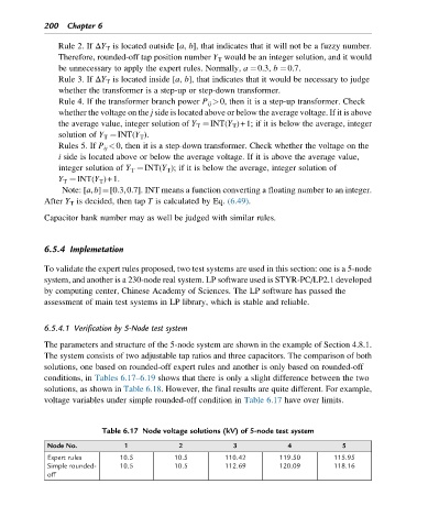
solutions, as shown in Table 6.18. However, the final results are quite different. For example,
voltage variables under simple rounded-off condition in Table 6.17 have over limits.
Table 6.17 Node voltage solutions (kV) of 5-node test system
Node No. 1 2 3 4 5
Expert rules 10.5 10.5 110.42 119.50 115.95
Simple rounded- 10.5 10.5 112.69 120.09 118.16
off