
Page 210 - Mathematical Models and Algorithms for Power System Optimization
P. 210
Discrete Optimization for Reactive Power Planning 201
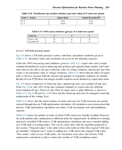
Table 6.18 Transformer tap location solutions (per-unit value) of 5-node test system
Node I2Node J Expert Rules Simple Rounded-Off
1–4 0.95 0.95
2–5 0.925 0.95
Table 6.19 VAR source solutions (group) of 5-node test system
Node No. 3 4 5
Expert rules 10 6 8
rounded-off 10 6 8
6.5.4.2 230-Node practical system
Fig. 6.8 shows a 230-node practical system, with basic calculation conditions given in
Table 6.20. All initial values and constraints are given by the planning engineer.
Under the 1995 forecasting load conditions given in Table 6.21, expert rules and a simple
rounded-off method are used to obtain tap ratio position and capacitor bank number. ΣΔU (per-
unit value) in the table is the sum of absolute value of voltage violations, and maxΔU (per-unit
value) is the maximum value of voltage violations. Table 6.21 shows that the effect of expert
rules is obvious, because both the amount and quantity of constraint violations are smaller.
Results of Case 952D show that integer-feasible solution can be obtained by expert rules alone.
Fig. 6.9 shows comparison of initial tap ratio, optimal tap ratio, and rounded-off tap ratio.
From Fig. 6.9A, only 10% of tap ratio solutions obtained by expert rules are different
from rounded-off ones. However, the effect of expert rules is quite different, as shown in
Table 6.21. Fig. 6.9B and Fig. 6.9C show that the initial tap ratio must be changed to meet the
requirement of the voltage level.
Table 6.22 shows that the initial number of nodes and costs for VAR allocation are greatly
reduced through discrete VAR optimization calculation. All calculation cases demonstrate that
discrete VAR optimization calculation can reduce VAR investment costs and installation
capacity.
Table 6.23 shows the number of nodes at which VAR sources are initially installed. However,
the node number after optimization is different from the original node. In addition to existing
and newly installed VAR sources, VAR optimization calculation also must consider adding
new VAR units to existing nodes. This can be easily done with the algorithm proposed in
this section. “Original nodes” in the table refers to the nodes at which the original VAR units
are installed. “Original+new” refers to adding new VAR unit to the original VAR nodes.
“New nodes” refers to new VAR nodes. All calculation cases show that discrete VAR
optimization calculation is able to reduce the number of VAR installation nodes.