
Page 298 - Mathematical Models and Algorithms for Power System Optimization
P. 298
290 Chapter 8
Therefore, in the course of actual control, it is necessary to rely on the norm reduction control
criterion as much as possible. As a matter of fact, it is sufficient to achieve this as far as
possible because strict conformance with the norm reduction control criterion is a sufficient
condition for overall system stability rather than a necessary condition. The simulation
calculation for the analog system indicates that, as long as the criterion is met as much as
possible, system stability will be satisfied.
In addition, it should be pointed out that, to simplify the calculation and better describe the
problem, the simplest models are used in both theoretical analysis and system simulation
calculation, the problems are idealized, and less technical details involved in realization are
considered. Theoretically, it will not affect the effectiveness of the conclusion, and it could
liberate us from numerous minor details. This is more favorable to the problem to be
clarified.
8.3 Basic Concepts of Control Criteria based on Local Control
To describe the physical background and requirements of transient stability control, a
simplified mathematical model and typical network of power system is given in Section 8.3.1;
the control countermeasure adopted for the power system is divided into two stages (emergency
and norm reduction), which are described in Sections 8.3.2–8.3.3.
8.3.1 Simplified Model and Typical Network of the Power System
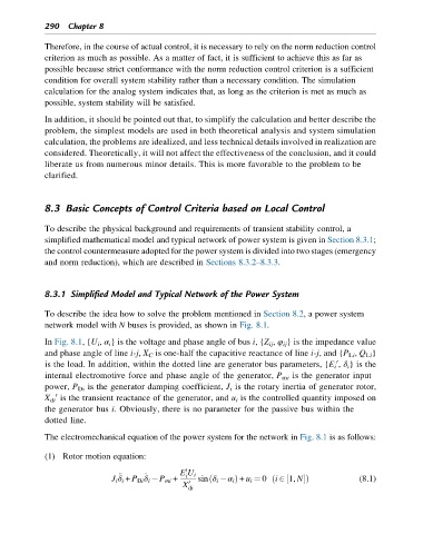
To describe the idea how to solve the problem mentioned in Section 8.2, a power system
network model with N buses is provided, as shown in Fig. 8.1.
In Fig. 8.1,{U i , α i } is the voltage and phase angle of bus i,{Z ij , φ ij } is the impedance value
and phase angle of line i-j, X C is one-half the capacitive reactance of line i-j,and {P Li , Q Li }
is the load. In addition, within the dotted line are generator bus parameters, {E i , δ i }is the
0
internal electromotive force and phase angle of the generator, P mi is the generator input
power, P Di is the generator damping coefficient, J i is the rotary inertia of generator rotor,
0
X di is the transient reactance of the generator, and u i is the controlled quantity imposed on
the generator bus i. Obviously, there is no parameter for the passive bus within the
dotted line.
The electromechanical equation of the power system for the network in Fig. 8.1 is as follows:
(1) Rotor motion equation:
0
E U i
€
_
J i δ i + P Di δ i P mi + i sin δ i α i Þ + u i ¼ 0 i 2 1, NÞ (8.1)
ð
½
ð
X 0
di