
Page 299 - Mathematical Models and Algorithms for Power System Optimization
P. 299
Local Decoupling Control Method for Transient Stability of a Power System 291
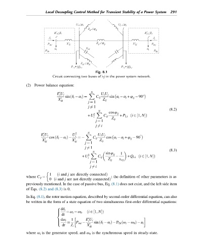
Fig. 8.1
Circuit connecting two buses of i-j in the power system network.
(2) Power balance equation:
0 N
E U i X U i U j
i sin α i α j + φ 90°
ð
sin δ i α i Þ ¼ C ij ij
X 0 Z ij
di
j ¼ 1
j 6¼ 1
(8.2)
N
X cosφ ij
+ U 2 C ij + P Li ð i 2 1, NÞ
½
i
Z ij
j ¼ 1
j 6¼ i
0 2 N
E U i U i X U i U j °
i
cos δ i α i Þ ¼ C ij cos α i α j + φ 90
ð
ij
X 0 X 0 Z ij
di di j ¼ 1
j 6¼ 1
(8.3)
N sinφ
X ij 1
+ U 2 i C ij + Q Li ð i 2 1, NÞ
½
Z ij x cij
j ¼ 1
j 6¼ i
1 ð i and j are directly connectedÞ
where C ij ¼ ; the definition of other parameters is as
ð
0 i and j are not directly connectedÞ
previously mentioned. In the case of passive bus, Eq. (8.1) does not exist, and the left side item
of Eqs. (8.2) and (8.3) is 0.
In Eq. (8.1), the rotor motion equation, described by second-order differential equation, can also
be written in the form of a state equation of two simultaneous first-order differential equations:
8
dδ i
½
> ð i 2 1, NÞ
> ¼ ω i ω 0
dt
<
0
dω i 1 E U i
> i
> ¼ P mi ð ð
: sin δ i α i Þ P Di ω i ω 0 Þ u i
dt J i X 0
di
where ω i is the generator speed, and ω 0 is the synchronous speed in steady-state.