
Page 41 - Mathematical Models and Algorithms for Power System Optimization
P. 41
Daily Economic Dispatch Optimization With Pumped Storage Plant 31
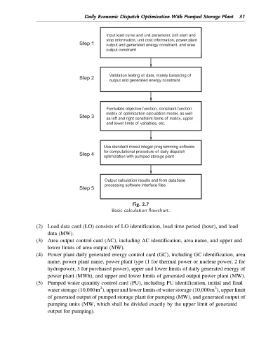
Input load curve and unit parameter, unit start and
stop information, unit cost information, power plant
Step 1 output and generated energy constraint, and area
output constraint
Validation testing of data, mainly balancing of
Step 2
output and generated energy constraint
Formulate objective function, constraint function
matrix of optimization calculation model, as well
Step 3 as left and right constraint items of matrix, upper
and lower limits of variables, etc.
Use standard mixed integer programming software
for computational procedure of daily dispatch
Step 4
optimization with pumped storage plant
Output calculation results and form database
processing software interface files
Step 5
Fig. 2.7
Basic calculation flowchart.
(2) Load data card (LO) consists of LO identification, load time period (hour), and load
data (MW).
(3) Area output control card (AC), including AC identification, area name, and upper and
lower limits of area output (MW).
(4) Power plant daily generated energy control card (GC), including GC identification, area
name, power plant name, power plant type (1 for thermal power or nuclear power, 2 for
hydropower, 3 for purchased power), upper and lower limits of daily generated energy of
power plant (MWh), and upper and lower limits of generated output power plant (MW).
(5) Pumped water quantity control card (PU), including PU identification, initial and final
3
3
water storage (10,000m ), upper and lower limits of water storage (10,000m ), upper limit
of generated output of pumped storage plant for pumping (MW), and generated output of
pumping units (MW, which shall be divided exactly by the upper limit of generated
output for pumping).