Page 481 - Mathematical Techniques of Fractional Order Systems
P. 481

Multiswitching Synchronization Chapter | 15  467


                   4
                   2
                   0                           –0.01
                y 1 ,x 3  –2                  y 1  - x 3
                  –4
                  –6                           –0.02
                  –8
                                               –0.03
                        20  40  60   80  100            0.5   1    1.5   2
                               t                               t      ×10 4

                   3
                                               –0.02
                   2
                y 1 ,x 1  1                   y 1  - x 1  –0.04
                                               –0.06
                   0
                                               –0.08
                  –1
                                                –0.1
                        20  40  60   80  100            0.5   1    1.5   2
                               t                               t      ×10 4
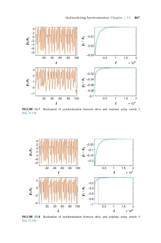
             FIGURE 15.7 Realization of synchronization between drive and response using switch 5
             (Eq. 15.15).


                    4
                    2                          –0.05
                     0                          –0.1
                  y 1 ,x 3  –2                y 1  - x 3  –0.15
                    –4
                    –6
                                                –0.2
                    –8
                         20  40   60  80  100           0.5   1   1.5   2
                                t                             t     ×10 4

                    2
                                                –0.2
                  y 1 ,x 2  0                 y 1  - x 2  –0.4
                                                –0.6
                    –2
                                                –0.8
                    –4                           –1
                         20   40  60  80  100           0.5   1   1.5   2
                                t                             t     ×10 4
             FIGURE 15.8 Realization of synchronization between drive and response using switch 5
             (Eq. 15.16).
   476   477   478   479   480   481   482   483   484   485   486