
Page 10 - Mechanical design of microresonators _ modeling and applications
P. 10
0-07-145538-8_CH01_9_08/30/05
Design at Resonance of Mechanical Microsystems
Design at Resonance of Mechanical Microsystems 9
X/X st
1/(2ξ)
2
0.707/( ξ)
ω 1 ω 2
ω
ω r
2ξω r
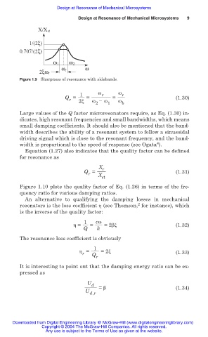
Figure 1.9 Sharpness of resonance with sidebands.
1 Ȧ r Ȧ r
Q = = = (1.30)
r
Ȧ íȦ
2ȟ
2 1 Ȧ b
Large values of the Q factor microresonators require, as Eq. (1.30) in-
dicates, high resonant frequencies and small bandwidths, which means
small damping coefficients. It should also be mentioned that the band-
width describes the ability of a resonant system to follow a sinusoidal
driving signal which is close to the resonant frequency, and the band-
4
width is proportional to the speed of response (see Ogata ).
Equation (1.27) also indicates that the quality factor can be defined
for resonance as
X r
Q = (1.31)
r
X
st
Figure 1.10 plots the quality factor of Eq. (1.26) in terms of the fre-
quency ratio for various damping ratios.
An alternative to qualifying the damping losses in mechanical
2
resonators is the loss coefficient Ș (see Thomson, for instance), which
is the inverse of the quality factor:
1 cȦ
Ș = = =2ȕȟ (1.32)
Q k
The resonance loss coefficient is obviously
1
Ș = =2ȟ (1.33)
r Q r
It is interesting to point out that the damping energy ratio can be ex-
pressed as
U d
= ȕ (1.34)
U d,r
Downloaded from Digital Engineering Library @ McGraw-Hill (www.digitalengineeringlibrary.com)
Copyright © 2004 The McGraw-Hill Companies. All rights reserved.
Any use is subject to the Terms of Use as given at the website.