
Page 11 - Mechanical design of microresonators _ modeling and applications
P. 11
0-07-145538-8_CH01_10_08/30/05
Design at Resonance of Mechanical Microsystems
10 Chapter One
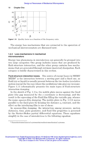
80
60 ξ = 0.1
Q 40 ξ = 0.25
20 ξ = 0.5
0
0 1 2 3 4 5
ξ = 1
β
Figure 1.10 Quality factor as a function of the frequency ratio.
The energy loss mechanisms that are connected to the operation of
mechanical microresonators are discussed next.
1.2.3 Loss mechanisms in mechanical
microresonators
Energy loss phenomena in microdevices can generally be grouped into
two large categories: One group includes losses that are produced by
fluid-structure interaction, and the other group contains loss mecha-
nisms that are generated through intrinsic (material) dissipation. Each
category is briefly characterized in this section.
Fluid-structure interaction losses. One source of energy losses in NEMS/
*
MEMS is the interaction between a moving part and a fixed one, as
fluid (air or liquid) is usually present between the two bodies in relative
motion (except for the case where the oscillations take place in vacuum).
Figure 1.11 schematically presents the main types of fluid-structure
interaction damping.
In the sketch of Fig. 1.11a, the mobile plate moves against the fixed
plate (the gap measured by the z coordinate is decreasing), and the
result is the squeezing of the fluid film filling the variable gap, whence
the name squeeze-film damping. The mobile plate in Fig. 1.11b moves
parallel to the fixed plate by keeping the distance z constant, and the
0
effect on the interlaying film is one of shear.
In squeeze-film damping, the interaction among pressure, motion
distances, time, plate geometry, and fluid film properties is governed
by the Navier-Stokes partial differential equations. These equations
simplify in the case of microdevices to the following equation:
* Nanoelectromechanical systems/microelectromechanical systems.
Downloaded from Digital Engineering Library @ McGraw-Hill (www.digitalengineeringlibrary.com)
Copyright © 2004 The McGraw-Hill Companies. All rights reserved.
Any use is subject to the Terms of Use as given at the website.