
Page 6 - Mechanical design of microresonators _ modeling and applications
P. 6
0-07-145538-8_CH01_5_08/30/05
Design at Resonance of Mechanical Microsystems
Design at Resonance of Mechanical Microsystems 5
m
x
c k
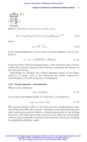
Figure 1.6 Single-degree-of-freedom mass-dashpot system.
. íȟȦt
0 /
x(t) = x cos(Ȧ t) + (x + ȟȦx ) Ȧ sin(Ȧ t) e (1.8)
0
d
0
d
d
where
2
Ȧ = 1 íȟ Ȧ (1.9)
d r
is the damped frequency of the system and the damping ratio ȟ is de-
fined as
ȟ = c c = c (2 mk) = c (2mȦ ) (1.10)
/
/
/ c
r
by means of the critical damping factor c c . The solution to Eq. (1.8) de-
scribes the natural response of the vibratory system in the absence of
the external forcing.
Depending on whether the critical damping factor is less than,
equal to, or larger than 1, the vibrations are called, respectively,
underdamped, critically damped, or overdamped.
1.2.2 Forced response — the resonance
When a force defined as
f (t) = Fsin(Ȧt) (1.11)
acts on the mass shown in Fig. 1.6, then Eq. (1.3) changes to
.. .
mx + cx + kx = f (t) (1.12)
The general solution of Eq. (1.12) is the sum of a complementary solu-
tion (which describes the system’s vibration at the natural frequency)
and a particular solution (which is vibration-generated at the driving
frequency). The latter part of the solution is also called the steady-state
solution and is generally analyzed in the frequency domain by studying
its amplitude and phase angle.
Downloaded from Digital Engineering Library @ McGraw-Hill (www.digitalengineeringlibrary.com)
Copyright © 2004 The McGraw-Hill Companies. All rights reserved.
Any use is subject to the Terms of Use as given at the website.