Page 15 - Mechanical design of microresonators _ modeling and applications
P. 15

0-07-145538-8_CH01_14_08/30/05


                                            Design at Resonance of Mechanical Microsystems

                              14   Chapter One
                                                               laminar flow


                                             δ
                                                               Stokes flow
                                       c
                                                  v              m
                                                                         k
                                                 t
                                        z 0
                                                             Couette flow

                                            Fixed plate (substrate)
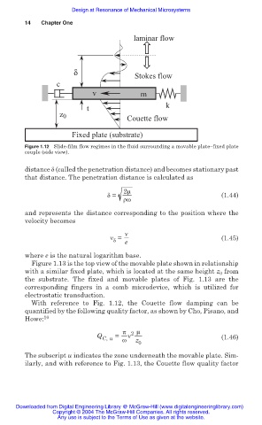
                              Figure 1.12 Slide-film flow regimes in the fluid surrounding a movable plate–fixed plate
                              couple (side view).

                              distance į (called the penetration distance) and becomes stationary past
                              that distance. The penetration distance is calculated as
                                                            2ȝ
                                                       į =                               (1.44)
                                                            ȡȦ

                              and represents the distance corresponding to the position where the
                              velocity becomes
                                                            Ȟ
                                                        Ȟ =  e                           (1.45)
                                                         į

                              where e is the natural logarithm base.
                                Figure 1.13 is the top view of the movable plate shown in relationship
                              with a similar fixed plate, which is located at the same height z 0  from
                              the substrate. The fixed and movable plates of Fig.  1.13 are  the
                              corresponding fingers in  a  comb microdevice, which  is  utilized for
                              electrostatic transduction.
                                With reference to Fig. 1.12, the Couette flow damping can be
                              quantified by the following quality factor, as shown by Cho, Pisano, and
                              Howe: 10
                                                           ʌ 2 ȝ
                                                    Q C, u  =  Ȟ                         (1.46)
                                                           Ȧ
                                                               z
                                                                0
                              The subscript u indicates the zone underneath the movable plate. Sim-
                              ilarly, and with reference to Fig. 1.13, the Couette flow quality factor


                           Downloaded from Digital Engineering Library @ McGraw-Hill (www.digitalengineeringlibrary.com)
                                      Copyright © 2004 The McGraw-Hill Companies. All rights reserved.
                                        Any use is subject to the Terms of Use as given at the website.
   10   11   12   13   14   15   16   17   18   19   20